#843 XNOR Gate with NAND Logic
Demonstrating how an XNOR gate may constructed solely from NAND gates.
Notes
The NAND boolean function has the property of functional completeness, meaning that any Boolean expression can be expressed with an equivalent expression using only NAND operations.
The NAND Truth Table:
| A | B | Q |
|---|---|---|
| 0 | 0 | 1 |
| 0 | 1 | 1 |
| 1 | 0 | 1 |
| 1 | 1 | 0 |
The XNOR Truth Table:
| A | B | Q |
|---|---|---|
| 0 | 0 | 1 |
| 0 | 1 | 0 |
| 1 | 0 | 0 |
| 1 | 1 | 1 |
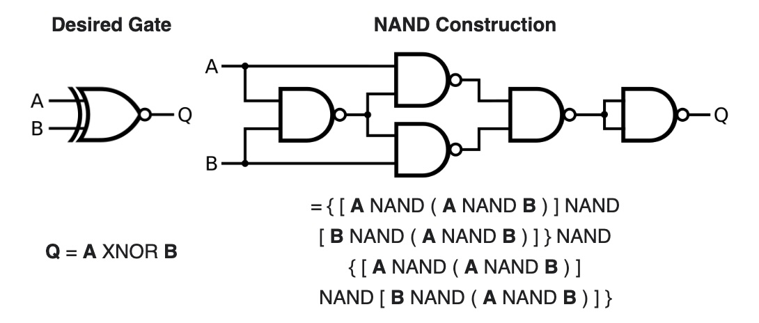
An XNOT gate can be constructed by simply inverting the output of an XOR gate. This construction has a propagation delay four times that of a single NAND gate.
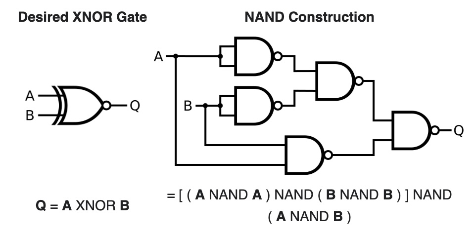
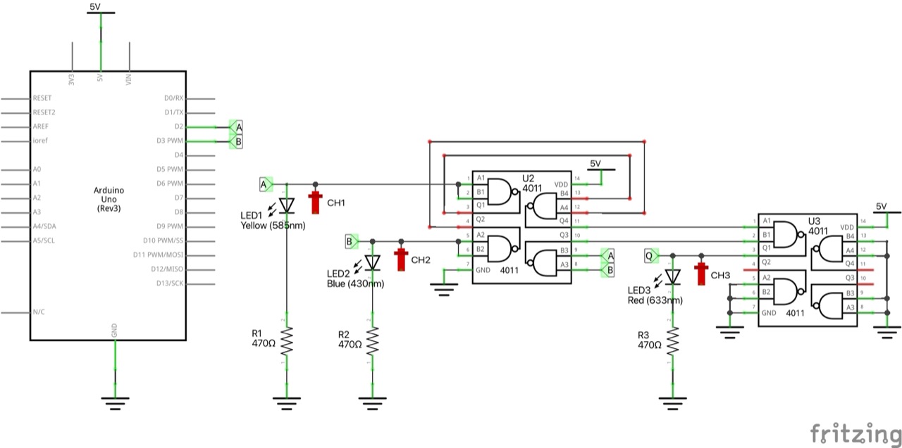
An improved design entails a propagation delay three times that of a single NAND gate and uses five gates. This is the circuit demonstrated on the breadboard.
Circuit Design
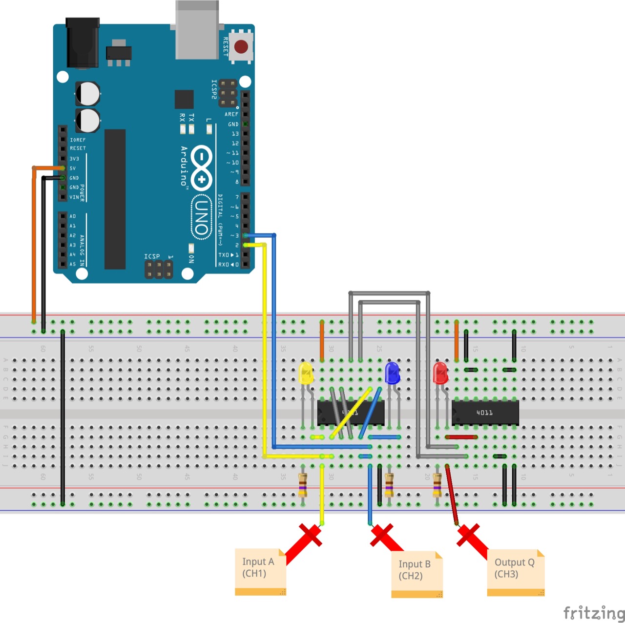
Designed with Fritzing: see XNOR.fzz.
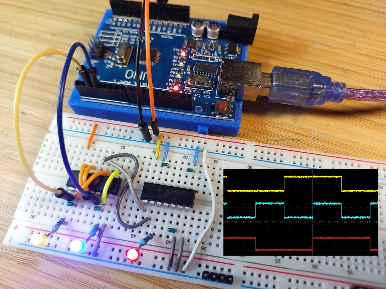
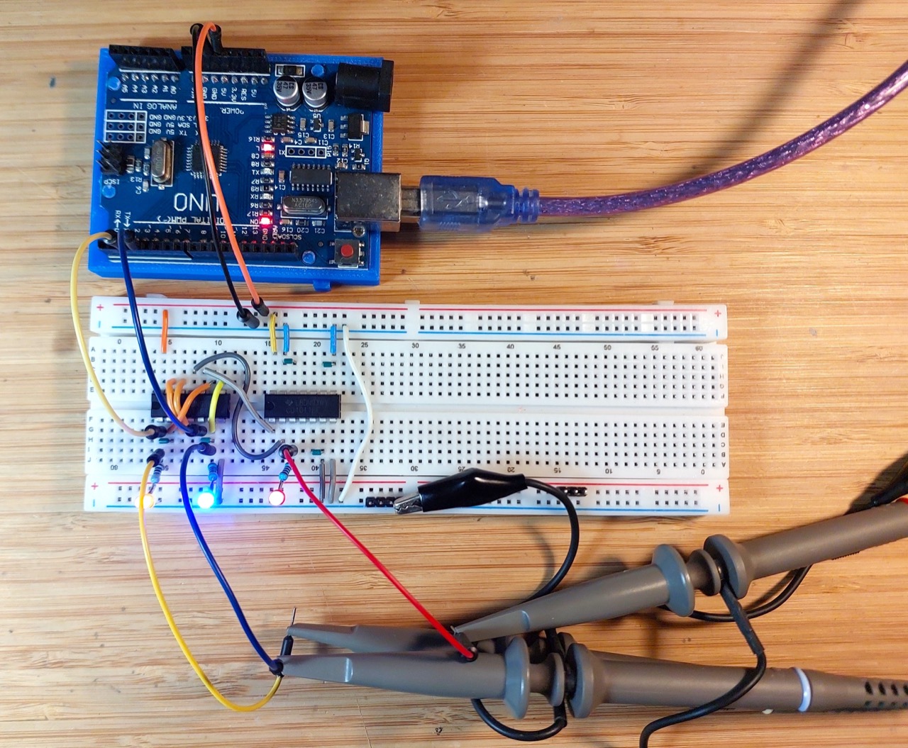
To demonstrate an XNOR gate made from NAND gates, I have the circuit constructed on a breadboard using the CD4011 Quad 2-Input NAND Buffered B Series Gate.
An Arduino is used to automate a demo cycle of inputs.
Inputs and outputs are indicated with LEDs, and captured with an oscilloscope.
The Sketch
See XNOR.ino.
The sketch simply automates the A, B inputs, cycling through all 4 possibilities.
Test Results
Here’s a scope trace capturing all 4 states, and demonstrating the the output is correct as expected. Traces are offset vertically for clarity.
- CH1 (yellow): input A
- CH2 (blue): input B
- CH3 (red): output Q