
#050 Girabot

Introduction
Girabot is my robot submission for the EE40LX Electronic Interfaces course run by BerkeleyX/Caltec.
The Brief
The requirements are quite nicely open-ended;-)
- Change behavior based on photocell input
- Beep buzzer audibly
- Change behavior when it hears a loud noise
- Spin motors to move itself
Final Video Demonstrations
Here is a video of the final build that demonstrates:
- Microphone/Buzzer/Motors: it dances to a tune in response to a load noise (clap)
- Photocell/Buzzer: it makes different noises when left/right photocells detect low light
- Motors: it randomly moves about when it’s got nothing better to do
A couple of things to note in this demo:
- I’ve connected a 9V 1A power supply in place of the battery (because I’d run all my batteries dry at the time of filming)
- I strapped on an Arduino Uno instead of the Nano as described elsewhere, because the Nano wasn’t available at the time
- I still haven’t got the “walking” right. But it tries!
Benchtest Walkthrough
The following video is a walkthrough of circuit functions on a breadboard prior to the final build:
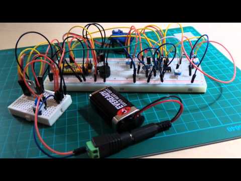
Photo Gallery
- the original stuffed toy
- breadboard benchtest
- circuit layout for transferring to protoboard
- the finished protoboard
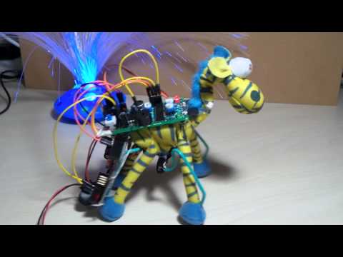
- Girabot!
Girabot Design - My Take on the Robot Brief
I’ve decided to diverge from the suggested design in a couple of ways. The most significant being that I’m basing the design on an Arduino Nano microcontroller instead of an MSP430, mainly because I had one on hand, but also because it offers a relatively small form factor without compromising processing and I/O capabilities.
I’m also varying components and some details of the design in smaller ways. The following sections describe how Girabot is designed to meet the primary criteria. Along the way, I’ve referenced the experiments concerning various aspects of robot operation.
Use-case: Girabot behaves in response to photocell input
The Girabot is equipped with two LDRs - a “left eye” and “right eye”. In the current build they are mounted near the eyes and detect light sensitivity roughly +/- 90 degrees from front. I was thinking about wiring up through the neck so the LDRs could actually “be” the eyes, but haven’t tried that yet.
When Girabot detects relative darkness to one side, it will:
- provide an audible chirp (a distinct sound for left or right)
- and change its movement towards the brighter side
LDR: Proof-of-concept/Explorations
The following mini-projects explore the use of LDRs in a Wheatstone Bridge
- LDR Comparator project - Low-light/proximity Trip Detector demonstration
- LDR Stereo Trip Detector - demo LM324 OpAmp as threshold trigger for stereo LDR/Wheatstone Bridge sensor
- StereoLightTrigger - demo an interrupt-driven method for responding to LDR light threshold triggers
Use-case: Girabot responds when it hears a loud noise
The Girabot is equipped with an electret microphone. When it detects a loud noise (such as a clap or whistle), it will unlock a “special behaviour”:
- Girabot will play a tune and dance along
- there will be at least one tune, maybe more…
Electret: Proof-of-concept/Explorations
- ElectretADC - plot the raw and amplified electret signal (LM324 preamp)
- ElectretTrigger - LM324-amplified electret input triggers a tune when over audio threshold
Implementation Notes
The electret microphone is biased to about 1V, and the AC component of the signal tapped via C1.
The microphone signal is then fed to the LM324 setup as a subtracting amplifier:
- positive input is set to Vcc/2 = 2.5V
- microphone signal fed to negative input
Vo = G1 * Vmic + G2 * Vcc
G1 = -R2/R1 = -220kΩ/2.2kΩ = -100
G2 = (R1 + R2)/R1 * R4/(R3 + R4) = (2.2kΩ + 220kΩ)/2.2kΩ * 22kΩ/(22kΩ + 22kΩ) = 75.5
When no microphone signal, we are reading Vcc/2 at the output.
But it is really sensitive to changes in the microphone signal. Basically every 1mV results in a 100mV change in the output.
The amplified signal is read by the Arduino, and when the signal exceeds a threshold, the Arduino triggers a tune played on the piezo speaker.
Use-case: Girabot beeps a buzzer audibly
Girabot plays a tune on a piezo buzzer. This special behaviour is unlocked when it hears a load noise.
Proof-of-concept/Explorations
- El Jarabe Tapatío - play The Mexican Hat Dance on a piezo buzzer with LM 386 amplification
- Popcorn - How to make a piezo buzzer even more annoying? Make it play popcorn!
Use-case: Girabot can move itself
The sample robot design does a “bouncy” thing with two DC motors. I experimented with motor controls or various types, but after deciding on the Girabot form factor I’m thinking it is more appropriate for Girabot to be a “walker” than a “bouncer”. The walker design I’m attempting uses a single motor - similar to insect BEAM designs - and I’m using a servo motor for better positional control.
A single-motor walker can be a difficult thing to make work with reasonable efficiency, as it relies on the right combination of weight distribution, friction surfaces and geometry. Challenge accepted!
Worst case, Girabot is going to be a crappy walking but an outstanding dancer..
Servos: Proof-of-concept/Explorations
- PWM Motor Control - tests PWM speed control of a DC motor driven by an Arduino
- ServoTest - test the positioning accuracy of a servo motor driven by an Arduino
Power
So far, power requirements for the various sub-systems are primarily 5V, with 9V alternative for the Arduino and the speaker sub-system:
- Arduino can take 9V unregulated or 5V regulated
- speaker subsystem tolerates a wide supply voltage. It will work with 5V, but should be louder with 9V
Power options include:
- 9V battery - allowing 9V and 5V rails
- 4 x AA/AAA - running everything at ~5V/6V, probably with zener regulated 5V source
Girabot is a pretty small build, so there’s not much room for batteries. Although the AA/AAA option would provided greater capacity, I think 9V is the way to go, purely from a size and weight perspective
So with a 9V source, I’m planning for two power rails in the system:
- 9V unregulated direct from the battery
- 5V via an LM7805 regulator
Given two power rails, there’s a question of which should be used to power the Arduino:
- 9V unregulated fed to VIN
- 5V regulated fed to 5V pin
Either can work, although it is perhaps more efficient to power the Arduino with 5V regulated, as this eliminates need to use the Arduino’s (now redundant) internal regulator.
Power: Proof-of-concept/Explorations
- LM317 Adjustable Regulator - test and graph the adjustable voltage supply
- LM7805 5V Regulated Supply - test and graph the voltage supply
- Zener Regulated 5V Source - test and graph a power supply regulated with a 1N4733 zener diode
Issues and Workarounds
Electrical Noise
The servo motors in particular appear responsible for putting considerable noise on the power rails. The main side-effect is on the speaker circuit (the noise gets amplified as audible sound).
Reasonable noise abatement was achieved by filtering the power supply with 10nF capacitors across the power connections to the motors and each OpAmp unit.
Sensitivity of the Audio Detection Circuit
The electret audio detection circuit has proven quite temperamental. In particular, it appears quite sensitive to the power supply. As batteries discharge, the signal-to-noise ratio reduces noticeably and requires readjustment of the noise threshold.
The main workaround is to ensure sufficient power supply. I think a better solution - not yet attempted - would be to implement some dynamic threshold that is sensitive to prevailing conditions.
Walk This Way
So my experiments with a single-servo walker are a “partial success”. It can’t yet walk efficiently in a forwards direction. I am expecting that some more adjustments of weight balance and friction pads on the feet would yield a better result.
But it does try!
Code
See Girabot.ino and associated *.h files for all the code.
Construction


Parts
| Ref | Part | Notes |
|---|---|---|
| U1 | Arduino Nano v3 | official site |
| IC1 | LM7805 | datasheet |
| IC2 | LM324N | datasheet |
| IC3 | LM386N-3 | datasheet |
| J2 | TowerPro SG90 | datasheet |
| S1 | DPST Switch | master switch; only one pole is used |
| C1 | 100μF electrolytic capacitor | filter on input power supply |
| C2 | 100nF ceramic capacitor | filter on 5V power supply |
| C3 | 100nF ceramic capacitor | audio in AC coupling |
| C4 | 100μF electrolytic capacitor | audio out AC coupling |
| C5 | 1μF electrolytic capacitor | mic in AC coupling |
| C6 | 10nF ceramic capacitor | bypass filter for noise-reduction |
| C7 | 10nF ceramic capacitor | bypass filter for noise-reduction |
| C8 | 10nF ceramic capacitor | bypass filter for noise-reduction |
| R1 | 200Ω(bright)-20kΩ(dark) LDR | 1/4 wheatstone bridge; typical range of 2kΩ-5kΩ under ambient conditions |
| R2 | 20kΩ trimpot | 1/4 wheatstone bridge |
| R3 | 4.7kΩ resistor | 1/4 wheatstone bridge |
| R4 | 4.7kΩ resistor | 1/4 wheatstone bridge |
| R5 | 1kΩ resistor | LED current limiter |
| R6 | 1kΩ resistor | LED current limiter |
| R7 | 200Ω(bright)-20kΩ(dark) LDR | 1/4 wheatstone bridge; typical range of 2kΩ-5kΩ under ambient conditions |
| R8 | 20kΩ trimpot | 1/4 wheatstone bridge |
| R9 | 4.7kΩ resistor | 1/4 wheatstone bridge |
| R10 | 4.7kΩ resistor | 1/4 wheatstone bridge |
| R11 | 22kΩ resistor | 1/2 voltage divider for mic non-inverting OpAmp input |
| R12 | 22kΩ resistor | 1/2 voltage divider for mic non-inverting OpAmp input |
| R13 | 100kΩ resistor | mic OpAmp feedback (fixed component) |
| R14 | 10kΩ resistor | electret mic biasing |
| R15 | 2.2kΩ resistor | mic inverting OpAmp input |
| R16 | 200kΩ trimpot | mic OpAmp feedback (variable component) |