
#048 StereoLightTrigger
A dual input low-light trigger: demonstrates an interrupt-driven method for an Arduino to respond to LDR light threshold triggers.
Notes
This demonstrates three circuit concepts:
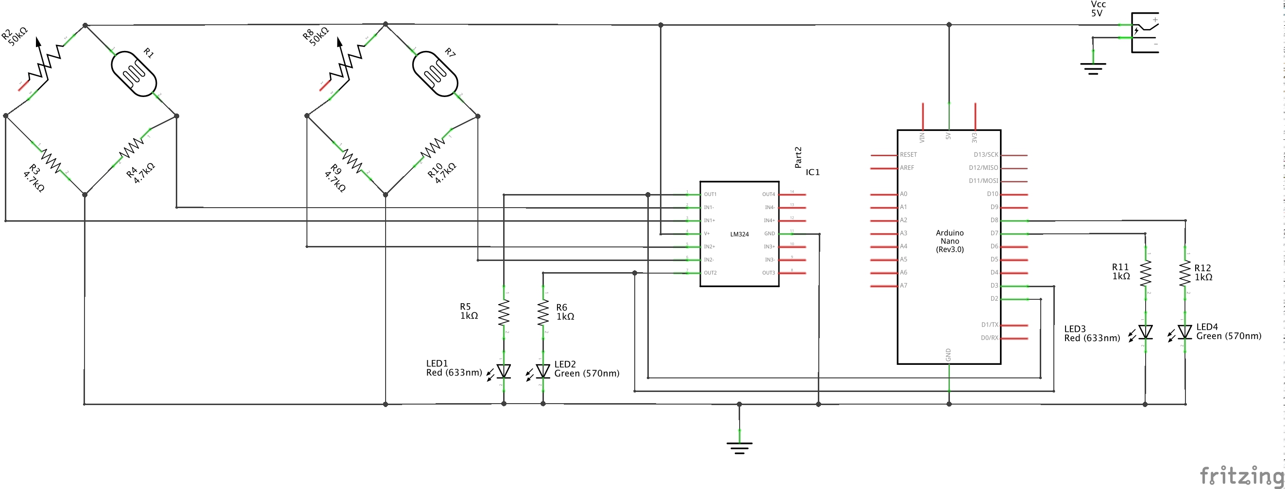
- a light sensor comprising a light-dependent resistor (LDR) and Wheatstone Bridge.
- a threshold detector using an OpAmp comparator.
- triggering an arduino function when light exceeds the OpAmp threshold
Two LDRs are in the circuit to provide dual or stereo light detection. There is nothing special about running two LDRs. The circuit could equally be built with just one if that is all the application required.
Calibrating the Wheatstone Bridge
The particular LDR used has a range of about 200Ω (bright light) to 20kΩ (dark). However the ambient light conditions used for testing the circuit exhibited a typical range of 2kΩ-5kΩ, hence 4.7kΩ is selected as the common resistor value in the bridge so that we can drive positive and negative voltages from the bridge. A variable resistor opposes the LDR, so that the actual threshold level can be trimmed.
The voltage differential measured across the bridge - from the base of the pot to the base of the LDR - will tend to rise in lighter conditions as the LDR resistance drops. As conditions get darker, the LDR resistance rises until a point there the voltage differential will go negative.
Comparator
The voltage differential of the Wheatstone Bridge is fed to an OpAmp comparator (an LM324 Low Power Quad Op-Amp). By feeding the LDR end of the differential to the negative input of the comparator, it acts as a low-threshold trigger. Reversing the inputs to the comparator could be used for a high-threshold trigger.
Arduino Triggering
While it would be completely OK to sample the OpAmp outputs in a loop, in this case we are using hardware interrupts to trigger when each the OpAmp output transits from low to high (RISING interrupt).
The interrupt service routine simply sets a flag corresponding to the LDR that activated.
The flags are then used and cleared by the main script when it gets around to checking LDR status. For demonstration purposes, a high flag is used to switch a corresponding indicator LED so that it is possible to see when an LDR interrupt has been successfully processed.
Behaviour
For plots of received light to triggering, see the LDR Comparator project project. It uses the same LDR wheatstone Bridge and monitors results with an Arduino.
Construction
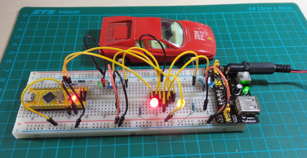
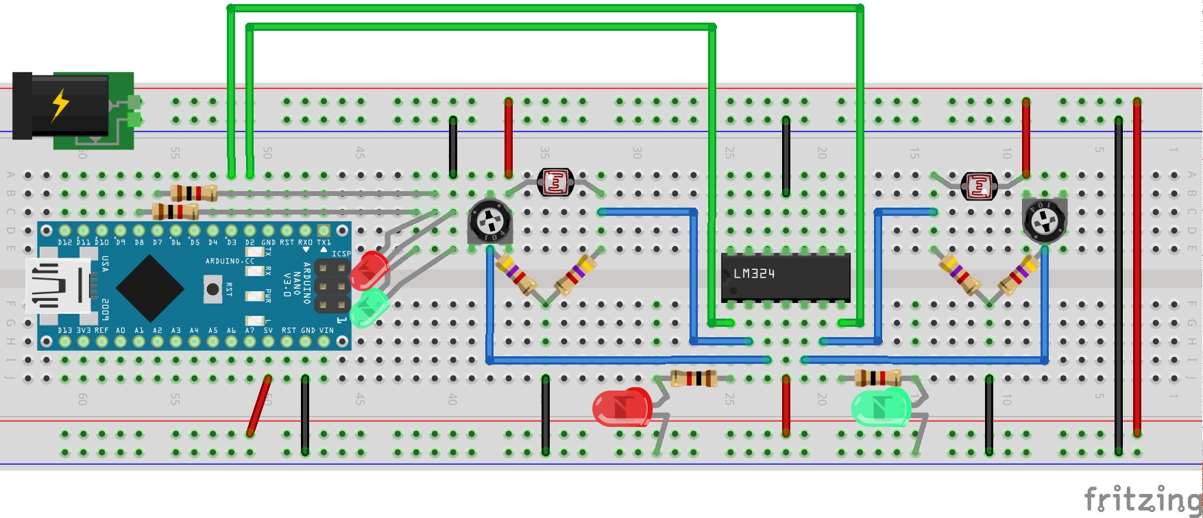
The build uses an Arduino Nano on a breadboard, with all components powered by an external 5V regulated supply.
Credits and References
- LM324 datasheet - Low Power Quad Op-Amp
- Properly terminating an unused op amp
- A similar application of an OpAmp is in “Project 06 - Hi-Lo Trip Detector” from Beginning Digital Electronics Through Projects