#844 MUX Gate with NAND Logic
Demonstrating how a MUX gate may constructed solely from NAND gates.
Notes
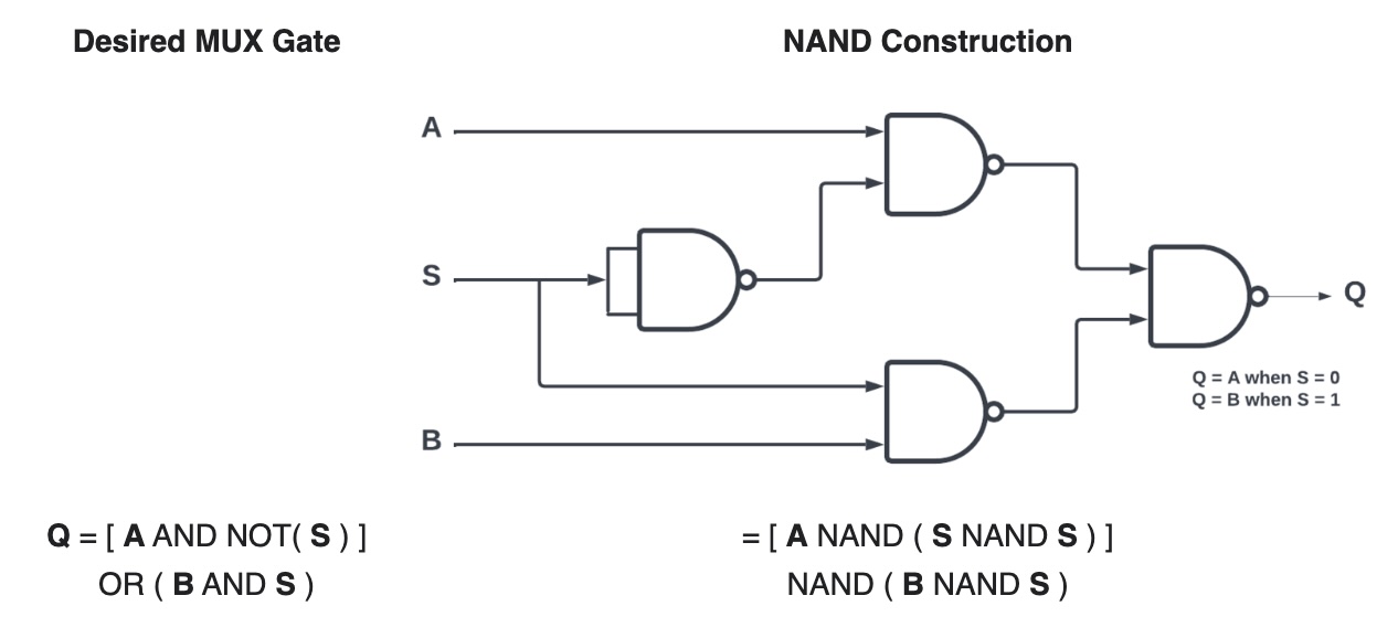
A multiplexer or a MUX gate is a three-input gate that uses one of the inputs, called the selector bit, to select one of the other two inputs, called data bits, and outputs only the selected data bit.
The MUX Truth Table:
| A | B | SEL | Q |
|---|---|---|---|
| 0 | 0 | 0 | 0 |
| 0 | 1 | 0 | 0 |
| 1 | 0 | 0 | 1 |
| 1 | 1 | 0 | 1 |
| 0 | 0 | 1 | 0 |
| 0 | 1 | 1 | 1 |
| 1 | 0 | 1 | 0 |
| 1 | 1 | 1 | 1 |
A MUX gate can be made with NAND gates as follows:
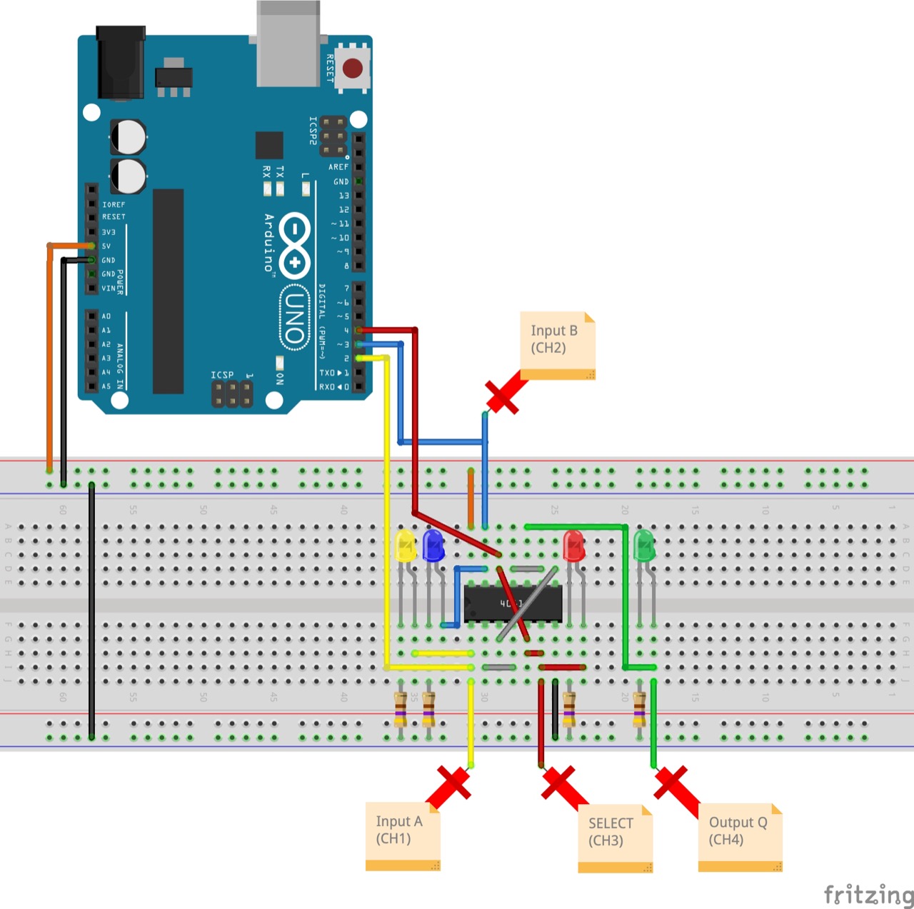
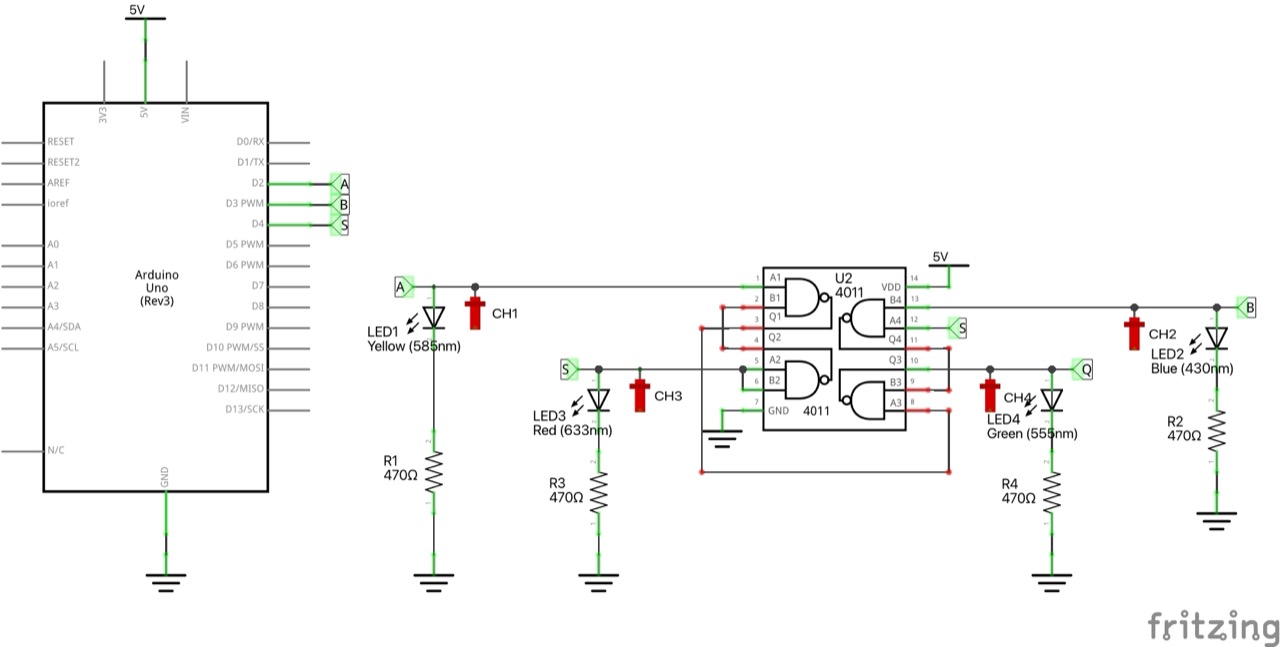
Circuit Design
Designed with Fritzing: see MUX.fzz.
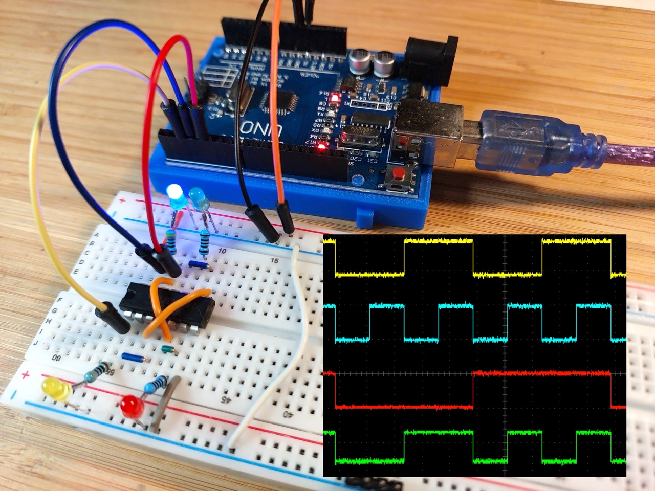
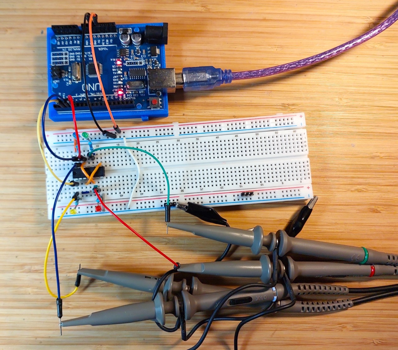
To demonstrate a MUX gate made from NAND gates, I have the circuit constructed on a breadboard using the CD4011 Quad 2-Input NAND Buffered B Series Gate.
An Arduino is used to automate a demo cycle of inputs.
Inputs and outputs are indicated with LEDs, and captured with an oscilloscope.
The Sketch
See MUX.ino.
The sketch simply automates the A, B, SEL inputs, cycling through all 8 possibilities.
Test Results
Here’s a scope trace capturing all 8 states, and demonstrating the the output is correct as expected. Traces are offset vertically for clarity.
- CH1 (yellow): input A
- CH2 (blue): input B
- CH3 (red): Selector
- CH4 (green): output Q