
#406 Custom CH340G USB to UART interface
Build a USB to TTL serial interface on a breadboard using the CH340G interface chip, and use it to program Arduino sketches on an ATmega328P.

Notes
The CH340G is a USB to UART Interface chip. It is often used as a cheap alternative to more established brands and products such as the FTDI FT232RL. The CH340G is commonly found in:
- Arduino Nano clones
- USB to Serial adapters
In this project, I’d like to see how easy it is to build a USB to Serial interface on a breadboard. To test it out, I’ll use it program Arduino sketches on an ATmega328P.
CH340G Key Specs
CH340 is produced by WCH 江苏沁恒股份有限公司 (Jiangsu Yuheng Co., Ltd.). It is a series of USB adapters - with variants providing serial, parallel or IrDA interfaces. The CH340G supports serial with common flow control signals.
Key features:
- USB 2.0
- Supports common flow control signals RTS, DTR, DCD, RI, DSR and CTS.
- Supports RS232, RS422 and RS485 with external level shifting components.
- Baud rate range from 50bps to 2Mbps.
- 5V and 3.3V operation.
Pinout:
| Pin | Name | Description |
|---|---|---|
| 1 | GND | Ground. Connect to the ground pin of USB bus |
| 2 | TXD | UART Data Transmit output |
| 3 | RXD | UART Data Receive input |
| 4 | V3 | Internal 3.3V reference for USB physical layer |
| 5 | UD+ | USB D+ signal |
| 6 | UD- | USB D- signal |
| 7 | XI | Crystal oscillator input |
| 8 | XO | Crystal oscillator output |
| 9 | CTS# | UART flow control: Clear to Send |
| 10 | DSR# | UART flow control: Data Set Ready |
| 11 | RI# | UART flow control: Ring In |
| 12 | DCD# | UART flow control: Data Carrier Detect |
| 13 | DTR# | UART flow control: Data Terminal Ready |
| 14 | RTS# | UART flow control: Request to Send |
| 15 | R232 | Auxiliary RS232 enable. Active high, internal pull down |
| 16 | VCC | Supply rail for the chip |
Notes:
- V3: Decouple with a 4.7-20nF capacitor when in 5V operation, or tie to VCC when in 3.3V operation.
Drivers and Setup for MacOSX
- see the official MacOSX setup notes
- if the Arduino has an FTDI instead of CH340G, if necessary install the FTDIUSBSerialDriver_v2_2_18.dmg
- see the arduino forum - general discussion and updates on the issue of USB drivers
CH340G Drivers
If the CH340G serial chip is not recognised my MacOSX, a driver is required. See:
- How to use cheap Chinese Arduinos that come with with CH340G / CH341G Serial/USB chip - a great guide.
- Updated driver (Sierra-compatible) is available at github.com/adrianmihalko/ch340g-ch34g-ch34x-mac-os-x-driver
- There also seems to be a professional drive kit available (at cost) from https://www.mac-usb-serial.com/
I’ve “cached” copies of the drivers I’ve used in the past in the drivers folder:
- CH341SER_MAC.ZIP
- CH34x_Install_V1.3.zip - latest version I’ve used
Chips and DIPs
I have some CH340G chips in SOP-16 package (from a seller on aliexpress). I’ve mounted one on a DIP adapter, and found a micro-USB breakout:

Examining a Commercial CH340 USB-Serial Adapter
I have a CH340G USB adapter that I got along with an Arduino mini, so I took a closer look to see if it used the CH340G chip in any unexpected ways.
Tracing the circuit, it turns out to be very straight-forward. A few things to note:
- the 3.3V/5V selector actually just enables/disables a 662K 3.3V regulator to supply the outbound power rail. It does not switch the operating voltage of the CH340G itself (or the data levels)
- includes a power indicator LED, and a transmit indicator LED
- has 1kΩ resistors inline the RX/TX lines; not particularly sure why (not mentioned in the CH340G data sheet)
- lots of ceramic bypass capacitors. I’m not sure of the actual capacitance values.


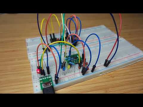
Building the CH340G Interface on a Breadboard
On one breadboard, I have a basic 5V CH340G setup:
- RX and TX LEDs; Power LED
- DTR, TXD and RXD connected on the serial side
On another breadboard, I have an ATmega328 (with Arduino bootloader) wired up for programming. See LEAP#405 ATmegaSerialProgrammer for more on programming over serial.


Here’s a quick demo (uploading a sketch). I’m programming the ATmega328 with the UsbUartCH340G.ino sketch - a simple blink variant that also sends bursts of serial output (to exercise the RX LED).
A Protoboard CH340G Demonstration
A final prototype before doing anything more serious - I’ve switched to SMD components and built up for testing on some protoboard with DIP adapters. A few changes to the design:
- added a 500mA resettable polyfuse on the USB supply
- connected both DTR and CTS lines to the 6-pin device adapter
- bumped up the LED current-limiting resistors to 2.7kΩ
The device pinout sequence I’ve selected is as follows. This suits some devices, but may need wires crossed for others.
| Pin | Name | Note |
|---|---|---|
| 1 | DTR | |
| 2 | RXD | Connects to TX on the device |
| 3 | TXD | Connects to RX on the device |
| 4 | VCC | |
| 5 | CTS | |
| 6 | GND |


Here’s a sketch of the layout I used:
