
#444 555 Diode Steering
Using diode steering to achieve adjustable duty cycle at fixed frequency in a 555 Timer astable oscillator.

Notes
The classic 555 Timer astable circuit can be made adjustable by using variable resistors. However it is very difficult to make duty cycle adjustments independent of frequency. One approach is covered in LEAP#145, but it requires some careful calculation to adjust R1 and R2 in correct proportions to adjust duty cycle without affecting frequency.
Another approach demonstrated here is to use “steering diodes” across a variable resistor so that charge and discharge resistance can be adjusted without affecting the mean resistance (and thus frequency) of the circuit.
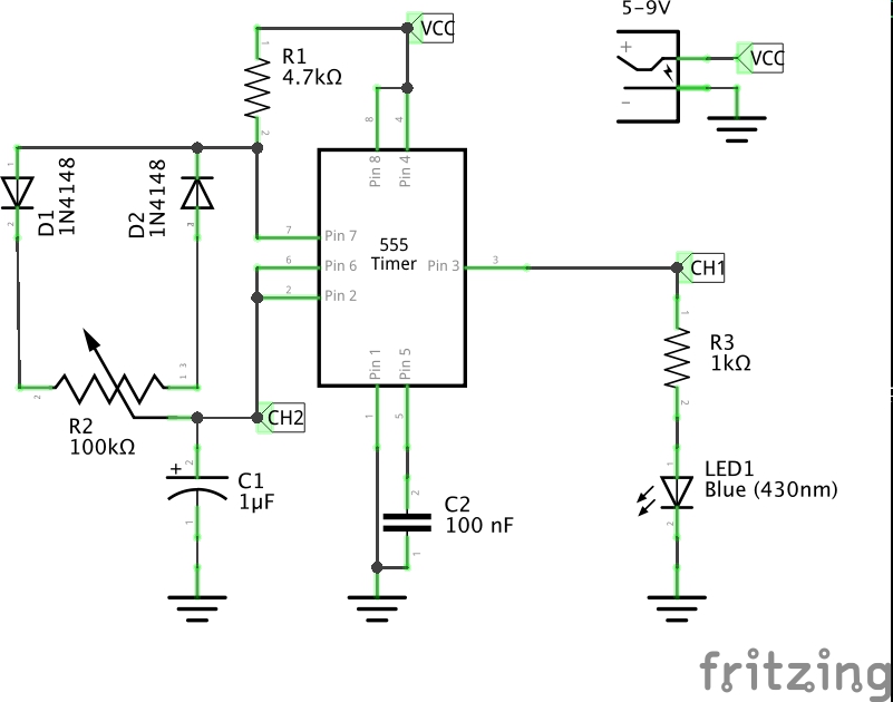
Circuit
In this circuit, charge and discharge paths are steered by diodes. Given a duty cycle proportion of D:
- charge: R1 through D1, portion of R2 = D x R2, to C1
- discharge: C1 through portion of R2 = (1 - D) x R2, D2 and to ground via pin 7
When duty cycle is 50% (i.e. R2 pot set half-way), the circuit is essentially identical to the standard astable but with R2 at half its value if one ignores the diodes. So the standard astable frequency calculation should be a reasonable approximation of frequency.
R1 should be kept small compared to R2 to ensure the widest duty cycle range, but not so small that excessive current is drawn during discharge.
With R1 = 4.7kΩ, R2 = 100kΩ pot, and C1 = 1µF, I would expect frequency to be around 13.75Hz with duty cycle ranging from around 4.5% to almost 100%.
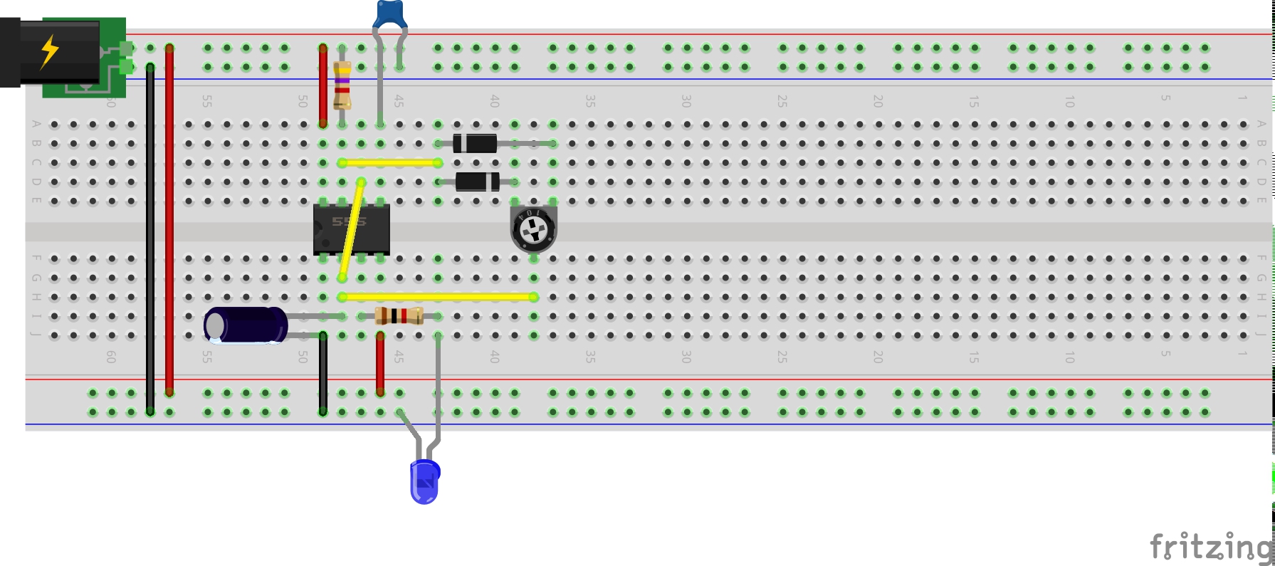
Designed with Fritzing: see DiodeSteering.fzz.
Results
In these traces, CH1 (yellow) is tracing the output, and CH2 (blue) to voltage at the 555 trigger/threshold:
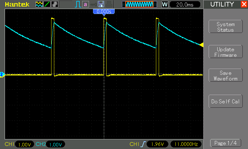
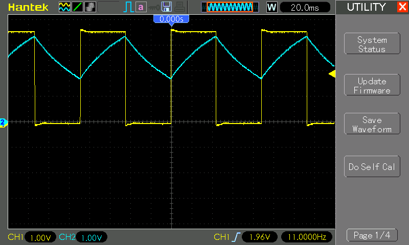
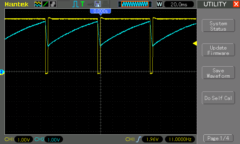
Some measurements, showing that actual frequency is a little off the predicted 13.75Hz but remains quite stable over the full duty cycle range:
| Duty | Actual Frequency |
|---|---|
| 5.1% | 10.82Hz |
| 50.0% | 10.52Hz |
| 95.0% | 10.70Hz |
Testing some other capacitor values:
| C1 | Actual Frequency | Predicted Frequency |
|---|---|---|
| 100nF | 164Hz | 137Hz |
| 10nF | 1.4kHz | 1.37kHz |
| 1 nF | 10.1kHz | 13.7kHz |
Credits and References
- LM555 Datasheet
- Designing 555 Astables - https://www.learnabout-electronics.org/Oscillators/osc44.php
- 555 Pulse Generator Circuit - https://www.electroschematics.com/5834/pulse-generator-with-555/