
#145 Variable Duty-Cycle 555 Timer
Test a 555 oscillator circuit that allows easy manual duty cycle adjustment while minimising the change to frequency.
Here’s a quick video of the circuit in action, in which the basic frequency has been slowed to around 2 Hz so that the duty cycle variation is clearly visible:

Notes
For many applications we want variable duty cycle while maintaining a fixed frequency.
The basic 555 timer astable configuration allows for duty cycles from ~50% to near 100%, and wide frequency range from <1Hz to hundreds of kHz. However, it is difficult to adjust duty cycle without affecting frequency and vice versa. This circuit is one approach for achieving continuously variable duty cycle while maintaining a relatively fixed frequency.
The formulae for calculating timings are given in the 555 datasheet:
t(high) = 0.693 x (R1 + R2) x C1
t(low) = 0.693 x R2 x C1
frequency = 1.44 / ((R1 + 2 x R2) x C1)
duty cycle high % = t(high) : t(low) = (R1 + R2)/(R1 + 2 * R2)
In order to adjust duty cycle without adjusting frequency, it follows that:
- if we increase R1 by ∆Ω, we must reduce R2 by ∆/2 Ω
- if we decrease R1 by ∆Ω, we must increase R2 by ∆/2 Ω
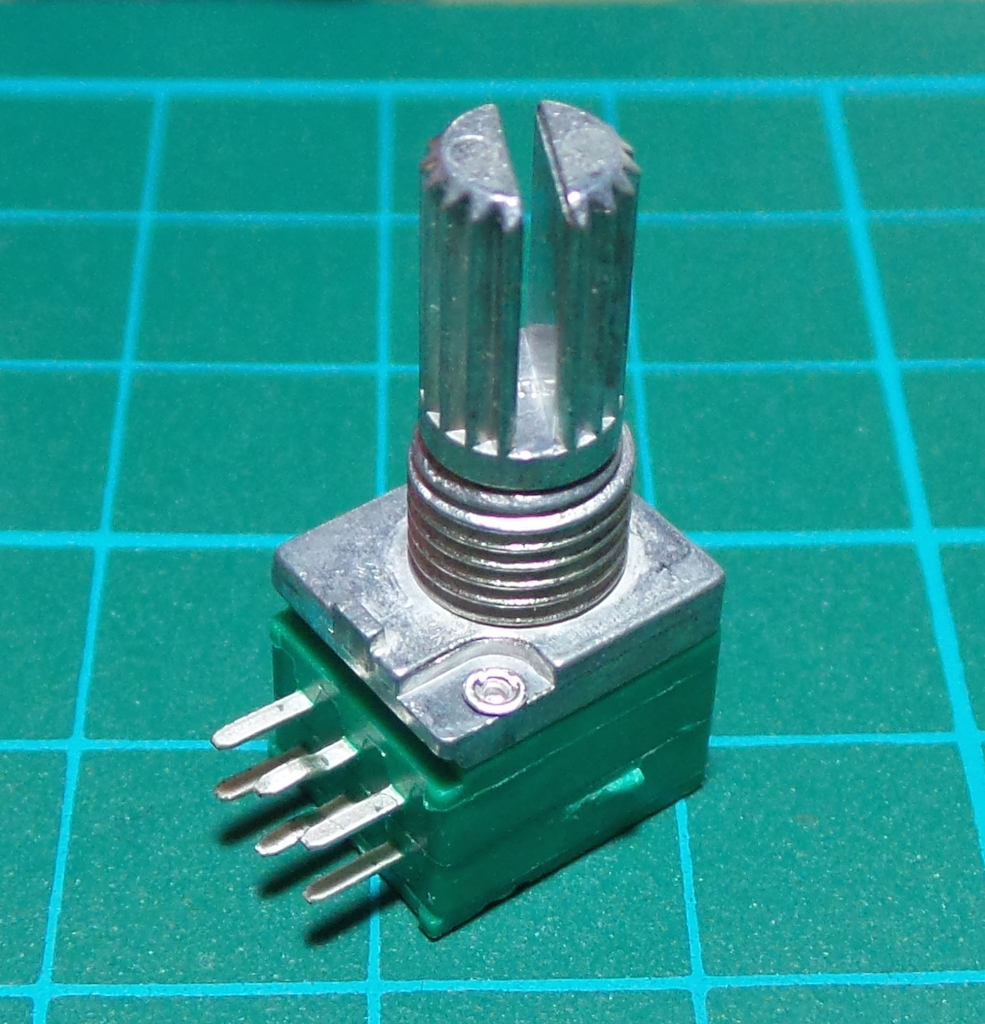
My objective here is “easy manual duty cycle adjustment” so I just want one control. This sounds like a job for a dual pole potentiometer. NB: an alternative approach with diode-controlled discharge circuit is covered on the learnabout-electronics site.
If I had a dual-pole pot with one core of say 50kΩ and the other of 25kΩ, that would be perfect. Unfortunately I don’t. But I do have a 50kΩ dual pole. So I just need to configure it so one pole has its resistance halved.
One approach is to put one core in parallel with a fixed 50kΩ resistor. This results in a slightly non-linear relationship between the limits, so it’s only an approximation:
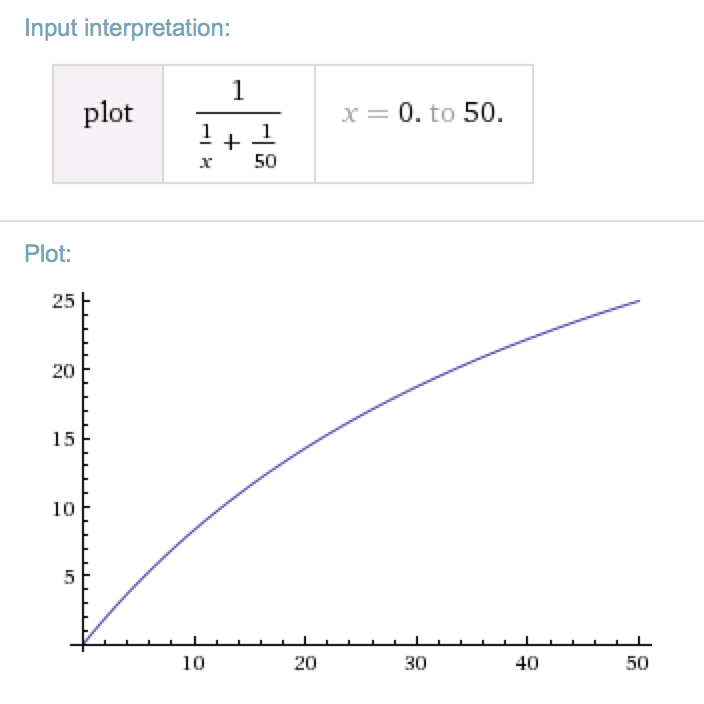
Here are the predicted minimum, maximum and mid-point duty cycles and corresponding frequency:
| Set | R1 | R2 | C1 | Duty Cycle High % | Frequency |
|---|---|---|---|---|---|
| min | 1kΩ | 35kΩ | 10nF | 51% | 2028Hz |
| mid | 26kΩ | 27kΩ | 10nF | 67% | 1800Hz |
| max | 51kΩ | 10kΩ | 10nF | 86% | 2028Hz |
The maximum frequency drift occurs near the midpoint, when R2 equals 26.67kΩ. It’s only 11% down, which is about as accurate as I could hope for, in return for a duty cycle being continuously variable from 51% to 86%.
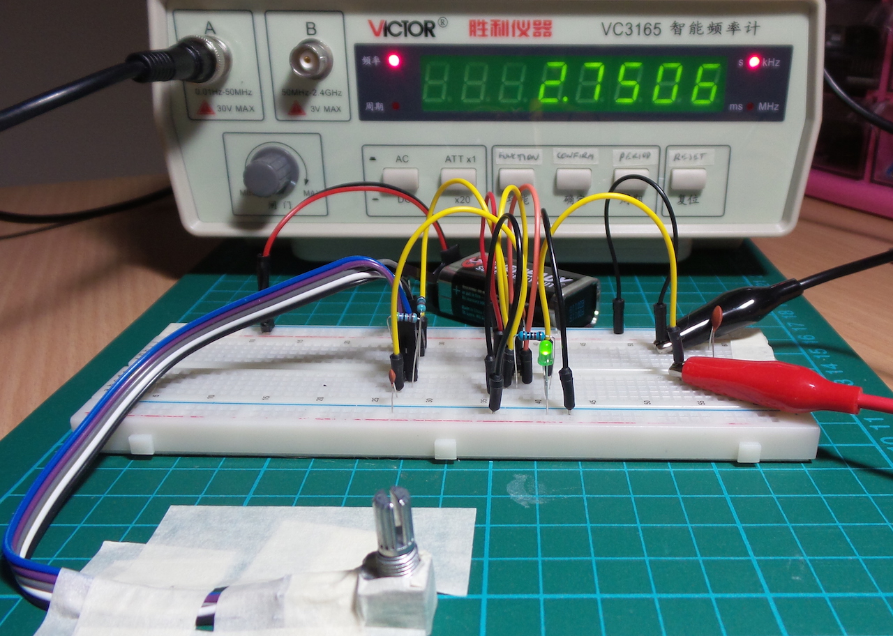
Actual Results
It turns out my 50kΩ dual-pole pot only goes to a max of about 44kΩ. So I’m using a parallel R2 resistor of 47kΩ and my R1/R2/C1 values are slightly off theoretical. According to my frequency counter, the circuit is running slightly faster than predicted by theory. However the stability of the frequency, and the variation as the resistance is changed are as expected.
| Set | R1 | R2 | C1 | Duty Cycle (calc) | Frequency (calc) | Frequency (actual) |
|---|---|---|---|---|---|---|
| min | 970Ω | 32.3kΩ | 10nF | 51% | 2.2 kHz | 2.75 kHz |
| mid | 23kΩ | 24.9kΩ | 10nF | 65.8% | 2.0 kHz | 2.55 kHz |
| max | 45.1kΩ | 9.79kΩ | 10nF | 85% | 2.2 kHz | 2.75 kHz |
Visual Demo
To be able to see the duty cycle variation, I slowed the circuit down by replacing the 10nF C1 with a 10µF electrolytic capacitor. This would predict a basic frequency of around 2.2Hz. In practice, I’m seeing around 2Hz, as demonstrated in the video.
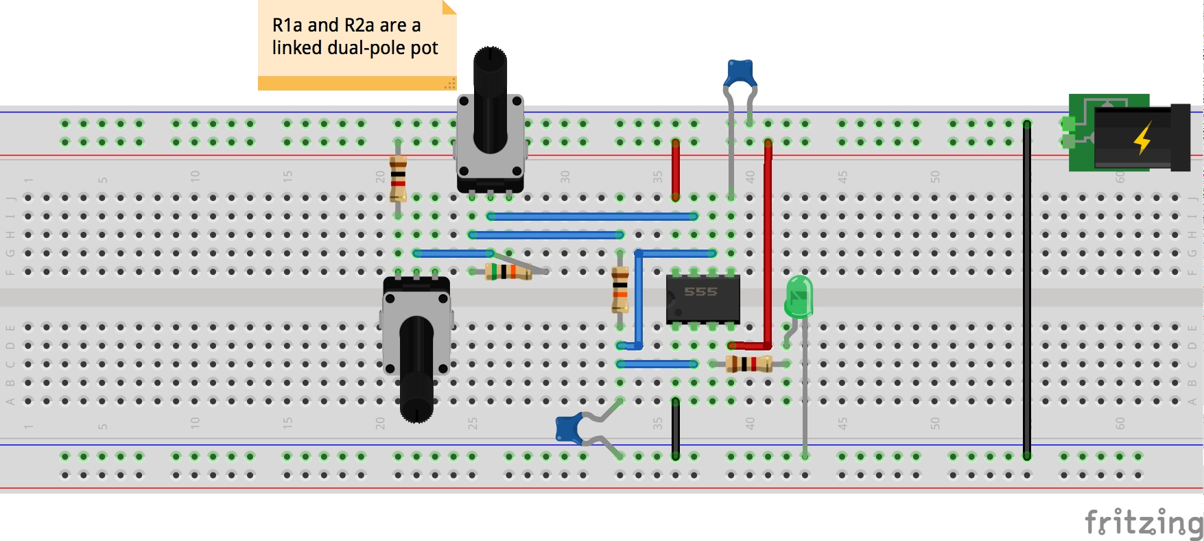
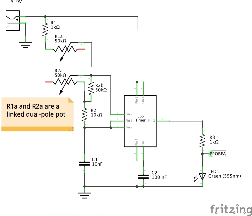
Construction
Designed with Fritzing: see VariableDutyCycle.fzz.
Credits and References
- LM555 Datasheet
- LEAP#016 AstableOscillator - the basic 555 timer astable circuit
- Visual 555 Calculator