
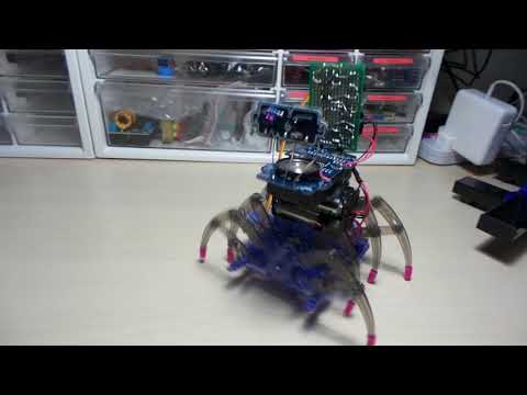
#354 SpiderBot
Boldport Club PissOff mutant offspring .. with spider legs and scuttling drive system.
Notes
Somewhere in my travels - IIRC, at [Five Below](diy spiderbot tech kit - I picked up a cheap “spider” robot kit .. I think because I wanted to examine how they drive the legs.
But for something a little more interesting, I thought I’d combine this with LEAP#290 Boldport PissOff. The result: a motion alarm that not only barks at you, but scuttles back and forth.
I think I’m channelling Sid from Toy Story ..
SpiderBot Kit
It’s a pretty cheap and basic kit, with a simple direct drive motor system that only does one thing. Good for about 15 minutes fun I guess!
the way they drive the legs with offset cams is pretty interesting, and impressive how they’ve managed to deliver it as a press-fit plastic kit.


Assembled the “normal” way…

Linking the PissOff
The PissOff has an active low “audio enable” signal that appears to be the most useful trigger to use to control the SpiderBot mechanism. It goes low (~0V) when the alarm is sounding. At other times it is at Vcc (~3V).
Unfortunately, there is no existing breakout for this signal, so it requires a bodge wire to tap the circuit. I attached at pin 1 of IC1 - the most accessible point.
Rewiring the SpiderBot drive system
I decided to use a simple oscillator to get the spider legs to go forward and reverse when triggered by the PissOff.
I’m using a 555 timer is configured for a fairly slow ~50% duty cycle of around 2.3s high / 2.3s low.
The difficulty turnout out to be getting it to control the motor. It is a terribly noisy motor in the SpiderBot! I tried a few other DC motors that I can drive quite effectively, but this one is totally obnoxious!
- it totally messes with the 555 timer circuit
- I’ve tried all manner of isolation:
- motor is switch with relay (with flyback diode)
- I’ve tried totally isolated electrics (no common ground). It didn’t help so the current incarnation does have a common ground.
- hefty smoothing/bypass capacitors
- importantly C7 capacitor across the relay switching FET was critical in getting anything decent
I refused to give up, though the results I have so far are not great. It does not have a balanced duty cycle:
- proceeds forward (motor relay normally open) OK
- but the reverse cycle (motor relay closed) is unstable - it gets tripped off very easily
Here’s what happens to my nice uniform 555 square wave when the motor is attached an under load:

Motor Controls
I’ve drawn up the motor control system with EasyEDA - the schematic source is here

Construction
And here’s the basic layout on to a protoboard “backpack” for the PissOff:


Credits and References
- LEAP#290 Boldport PissOff - the original Boldport Club PissOff project
- diy spiderbot tech kit - fivebelow
- GuoKe GK4078-3VDC
- 2N7000 datasheet
- LM555CN datasheet
- ..as mentioned on my blog