
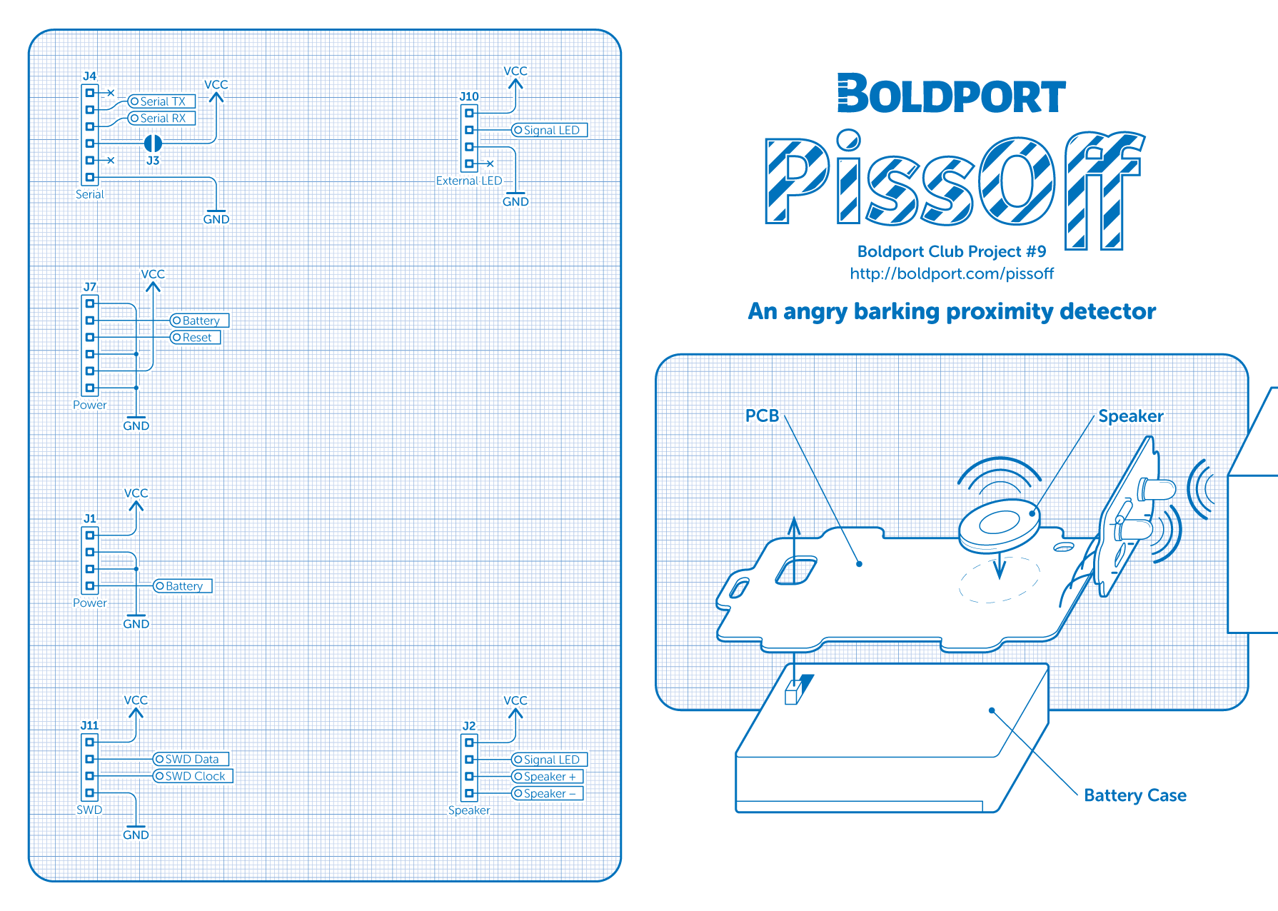
#290 PissOff
An angry barking blue-in-the-face mad proximity sensor - Boldport Club Project #9, November 2016.
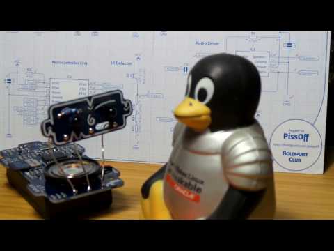
Here’s a quick video of it in action:
Notes
PissOff is the Boldport Club Project #9 (November 2016). It is a collaboration with LuckyResistor.
The core subsystems of the project:
- 3.3V linear regulator provides power for all components
- SD card adapter for audio file retrieval
- an infrared (IR) transmitter and receiver
- audio mixer and low-pass filter
- audio amplifier and speaker
- ARM Cortex-M0+ microprocessor to tie it all together

Parts
| Ref | Item | Qty |
|---|---|---|
| IC2 | Kinetis E series, ARM Cortex-M0+ SOIC20 32 bit MCU, NXP MKE04Z8VWJ4 | x1 |
| IC1 | Audio power amplifier SOIC8 IC, TI TPA301DR | x1 |
| J9 | microSD SMD card socket, MOLEX 1051620101 | x1 |
| VR1 | 50KΩ SMD trimmer, Bourns TC33X-2-503E | x1 |
| 29mm round speaker, Pro-signal ABS-205-RC | x1 | |
| 3xAAA battery holder with switch, TruPower SBH431-1AS | x1 | |
| IC3 | 3.3V LDO voltage regulator, Diodes AP2210K-3.3TRG1 | x1 |
| D1 | 5mm IR phototransistor (black lens), Multicomp OFT-5301 | x1 |
| D2 | 5mm IR diode (blue lens), Kingbright L-7113F3BT | x1 |
| IC4 | n-channel SOT23 SMD MOSFET transistor, ON Semiconductor 2N7002ET1G | x1 |
| C4,6 | 0.1µF 0805 SMD ceramic capacitor, Multicomp MC0805B104K500CT | x2 |
| C1,2,3,5,7 | 1µF 0805 SMD ceramic capacitor, Multicomp MC0805F105Z160CT | x5 |
| R2,3,8,10,12,13,14,15,16,18,19 | 8.2KΩ 0805 SMD resistor, Multicomp MCWR08X8201FTL | x11 |
| R4,6,7,22,23 | 1KΩ 0805 SMD resistor, Multicomp MCWR08X1001FTL | x5 |
| R9,11,spare | 220Ω 0805 SMD resistor, Multicomp MCWR08X2200FTL | x3 |
| R1,5,20,21,24,25,26 | 47KΩ 0805 SMD resistor, Multicomp MCWR08X4702FTL | x7 |
| R17 | 33Ω through-hole resistor, Multicomp MF25 33R | x1 |
| D3 | Yellow 0805 SMD LED, Kingbright KPT-2012YC | x1 |
| 20AWG wire, Belden 566-8020 | 14cm |

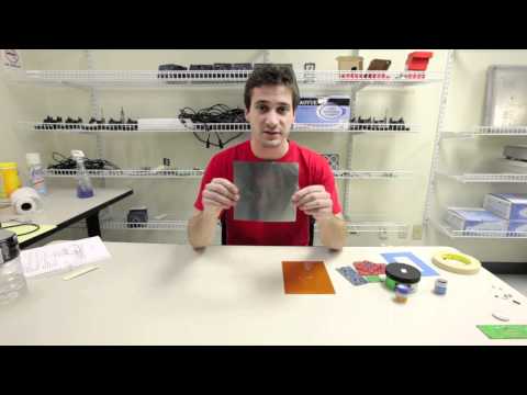
Using Solder Paste and Stencils
While you can hand-solder the project, it also presents a nice opportunity to experiment with reflow techniques.
I found this great tutorial from sparkfun, everything I need to know to do a decent job of my first reflow with stencil:
Reflow Assembly
I decided to try my hand at some reflow. I’m using the stencil from OSH Stencils, some 63/37 solder paste and a hand-held hot air gun.
Stencil and board taped down with kapton in an ad-hoc PCB frame:

Solder paste applied, all components mounted:

After reflow with hand-held hot-air gun:

At this stage I did a full continuity check on all soldered components to make sure the reflow had produced reliable connections. I only found two problems:
- one of the capacitors got dislodged at some point and wasn’t properly connected on one terminal
- pin 11 of the microprocessor wasn’t making a good connection
No problem - couple of dabs of solder paste and reflow - now all good!
Overall, the reflow assembly process worked brilliantly:
- much faster than I could have done it by hand soldering with an iron
- I doubt I could have soldered the SD card socket by hand without a great deal of pain
- the final result looks great - almost like it came out of a factory
Next to final assembly:
- through-hole components with an iron
- hot-glue for the speaker and battery pack attachment
And here it is, ready to test:

Code
The microcontroller comes preloaded with the correct code, and works out of the box. To investigate the sources, or compile a derivitive work, see the source code on GitHub.
First I’ll get this started with the preloaded code…
Preparing the SD Card
@fuchs has provided a PissOff default disk image with a barking dog sound. The RaspberryPi guide to installing disk images is a good resource for instructions no how to prepare the SD card. I’m using a Mac, so these are the appropriate instructions.
Using Disk Utility to verify and identify the SD card:

First Attempt
I first tried with a very old 128MB microSD card, formatted as “MS-DOS (FAT)” in the MacOSX Disk Utility tool.
Copying the disk image to the device:
$ diskutil list
...
/dev/disk3
   #:                       TYPE NAME                    SIZE       IDENTIFIER
   0:     FDisk_partition_scheme                        *127.1 MB   disk3
   1:                 DOS_FAT_32 UNTITLED                127.1 MB   disk3s1

$ diskutil unmountDisk /dev/disk3
Unmount of all volumes on disk3 was successful

$ sudo dd bs=1m if=disk.img of=/dev/rdisk3
0+1 records in
0+1 records out
342016 bytes transferred in 0.026458 secs (12926740 bytes/sec)

$ diskutil eject /dev/disk3
Disk /dev/disk3 ejected
So far so good, but no sound when I try it in the PissOff.
Note: read on for two solutions and the underlying problem finally identified and resolved.
Serial Debugging
Time to connect up a serial debugger! Serial connections are on J4. The PCB conveniently has offset holes, so a pin header can be simply inserted with press-fit. I’m using a USB Serial adapter with a 3.3v logic level mode. Only 3 wire connections are required:
| USD Serial Adapter | J4 |
|---|---|
| RXD | tx |
| TXD | rx |
| GND | gnd |
Here is the adapter connected:

The problem is immediately apparent. The disk is mounted but the processor can’t read any blocks. The troubleshooting guide is a good reference for the debug interface.

Second Attempt
From reports I’ve seen in the Boldport Slack, not all SD cards work with the PissOff. The main factor seems to be older/smaller capacity cards that probably don’t support SDHC correctly.
So I tried again with a newer 64Gb SD card, formatted as “MS-DOS (FAT)” in the MacOSX Disk Utility tool:
$ diskutil list
...
/dev/disk3
   #:                       TYPE NAME                    SIZE       IDENTIFIER
   0:      GUID_partition_scheme                        *67.1 GB    disk3
   1:                        EFI EFI                     209.7 MB   disk3s1
   2:       Microsoft Basic Data TEST                    66.9 GB    disk3s2

$ diskutil unmountDisk /dev/disk3
Unmount of all volumes on disk3 was successful

$ sudo dd bs=1m if=disk.img of=/dev/rdisk3
0+1 records in
0+1 records out
342016 bytes transferred in 0.026458 secs (12926740 bytes/sec)

$ diskutil eject /dev/disk3
Disk /dev/disk3 ejected
And it works! Here’s the serial debug output for an alarm sequence:

Trying again with an old SDIO Card
Here’s why the BoldportClub slack channel rules: the SD card support issue was finally resolved by @pastva:
I found why pissoff can't play files from small cards (2GB).
Serial debug revealed that READ_MULTIPLE_BLOCK (CMD18) returns error code.
I found that SDHC cards are addressed in terms of 512 byte blocks, non SDHC card expects byte address.
To fix it SDcard::startMultiRead method has to multiply startBlock by 512 for non SDHC cards (or << 9).
Then @fuchs created a non-SDHC card image: piss-off-disk-no-hc
I tried this image with the 128Mb SDIO card (that failed in my first attempt), and it works just fine!
Copying the image to the SD card:
$ diskutil list
...
/dev/disk2
   #:                       TYPE NAME                    SIZE       IDENTIFIER
   0:     FDisk_partition_scheme                        *127.1 MB   disk2
   1:                 DOS_FAT_32 UNTITLED                127.1 MB   disk2s1
$ diskutil unmountDisk /dev/disk2
Unmount of all volumes on disk2 was successful

$ sudo dd bs=1m if=disk_non_hc.img of=/dev/rdisk2
0+1 records in
0+1 records out
342016 bytes transferred in 0.274037 secs (1248064 bytes/sec)

$ diskutil eject /dev/disk2
Disk /dev/disk2 ejected
Successful initialisation and alarm with the new image on a very old 128Mb SD card:

So it turns out my older (failing) SD cards only supported SDIO, not SDHC.
Schematics
The schematic is nicely documented on the card includedin the kit. Note two errata:
- the IR LED is labelled D2 on the schematic but D5 on the PCB silkscreen
- IC2 pin labelling is a little off in the schematic: missing PTB4; PTB5,6,7 offset by one and an erroneous “Enable” label inserted
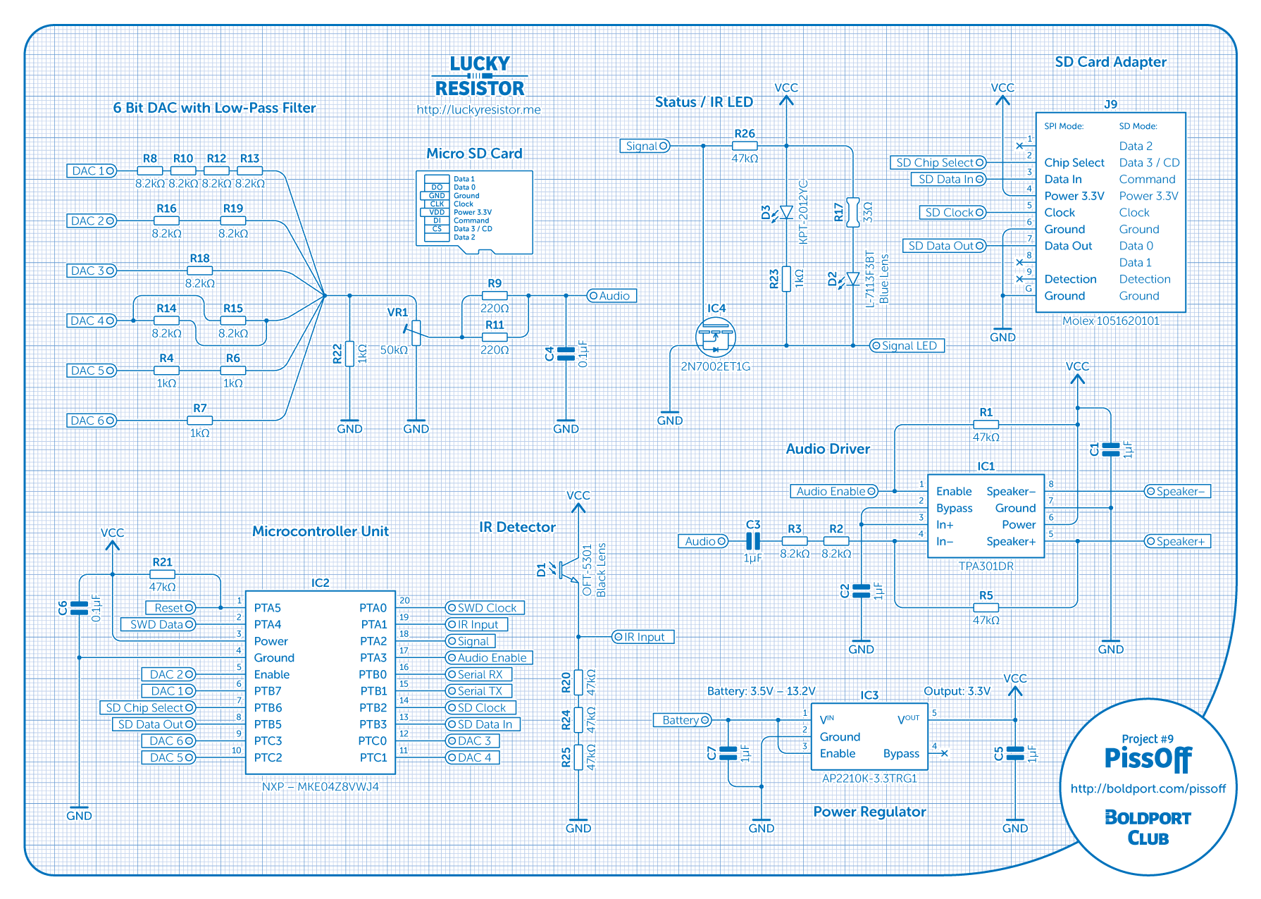
As part of verifying the circuit, I redrew the schematic in Fritzing:

Credits and References
- PissOff - in the Boldport shop
- PissOff - project page
- PissOff - OSH files on GitHub
- PissOff - club community site, packed with resources for the project
- PissOff source code
- PissOff default disk image
- installing disk images
- MicroSD - wikipedia
- SDIO, SDHC, and SDXC - wikipedia
- MKE04Z8VWJ4 datasheet
- TPA301DR datasheet
- AP2210K-3.3TRG1 datasheet
- 2N7002ET1G datasheet
- ..as mentioned on my blog