
#484 Crystal-Locked 455 kHz AM Oscillator
A crystal-locked 455 kHz carrier oscillator with fixed-frequency audio tone amplitude modulation (AM) for IF alignment.

Here’s a quick demo..
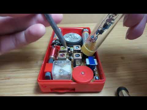
This shows alignment of the LEAP#462 HX108-2 AM kit.
Notes
Transformers in AM radios are generally aligned to an intermediate frequency of 455kHz, meaning that band-pass filters attempt to isolate the intermediate frequency carrier before extracting the signal.
A test signal at 455kHz modulated by an audio tone is therefore a useful bit of test equipment for audibly checking the alignment of the filters.
This project is a build of a very common modulated 455kHz design, and it works like a charm! One of the many sources for the design is a Silicon Chip article from Jan 2008 - The Minispot 455kHz Modulated Oscillator.
Circuit Design
This is a simple circuit in two basic parts:
- a 455 kHz crystal-locked oscillator providing the carrier
- an RC astable multivibrator running at an audible frequency that is used to modulate the carrier
The circuit works across a wide voltage range (from about 3V and up).

The frequency of the audio signal is determined by the values of R1, R2, C1 and C2 (making R1==R2, and C1==C2 maintains ~50% duty cycle). With R1 = R2 = 33kHz, possible values of C1/C2 include:
| C1, C2 | Predicted Frequency | Measured Frequency | Note |
|---|---|---|---|
| 47nF | 465Hz | 410Hz | As used in the original and many derivative designs |
| 22nF | 994Hz | 1.0kHz | What I decided to use |
The predicted frequency is calculated by:
f = 1/(ln(2) * ( R1 * C1 + R2 * C2))
See LEAP#049 for more on the RC oscillator design.
Breadboard Build
I initially tested the circuit on a breadboard with a 5V power supply.


The following traces capture the audio oscillator signal.
With 47nF capacitors / 410Hz:

With 22nF capacitors / 1.0kHz:

The resulting modulated output (captured with peak function to demonstrate the modulation):

Ugly Tubular Build!
I have (lots) of old solder tubes that I’ve been saving for a rainy day. This seemed to be a good opportunity to try and put them to use.
First step was to build the “business end” ugly style in a for that would fit in the solder tube. One thing I got a little off - I’d make the probe end longer next time, in order to get deep inside the guts of a radio.

One tube for the electronics, and two tubes to hold 4 x AAA (they just fit nicely)
All joined together, the thing is a bit of a beast, but it works just fine. The discoloration of the tube (and components inside) appears to be an unexpected CSI super-glue experiment! I used super glue to join the tubes, and the fumes appear to have attached themselves to any specs of dust or oil - no latent fingerprints tho!
Credits and References
- 455kHz IF Signal Generator with AM Modulation - source project write-up
- The Minispot 455kHz Modulated Oscillator - original Silicon Chip article, Jan 2008
- LEAP#462 HX108-2 AM kit