
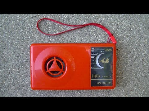
#462 HX108-2 AM Receiver
Build and analyse the HX108-2 superheterodyne AM MW radio receiver kit.

Notes
AM/MW radios are of very little use these days in Singapore. There is no local AM broadcasting, just a few stations from Indonesia and Malaysia that can be picked up if you’re lucky. However, there’s still a great deal that can be learned from studying simple AM superheterodyne circuits. I have built a similar kit before - the HX-6B, see LEAP#123 - but I probably know more than I did then, so I’m looking forward to this little opportunity to revisit similar ground.
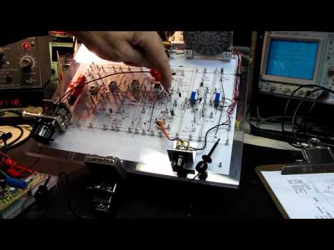
Although it’s possible to build the entire kit in under an hour, I decided to carefully follow a sub-system by sub-system build from audio out to RF in. Co-incidentally, K7QO is posting an excellent series covering the build of an HX108-2 at the same time … so I am heavily cribbing from there;-)
Tutorials and Resources
The HX108-2 is a pretty popular kit, and a number of very good tutorials can be found on YouTube describing construction and tuning. Here’s a selection…
K7QO HX108-2 AM Receiver: Theory and Construction
K7QO had a series covering the build that appears to have been subsequently re-cut into a series on RF Receivers. The main videos covering this particular radio are part 6 and 7:
RF RECEIVERS – 6 – Audio Amp, Driver and Demodulation Circuits

RF RECEIVERS – 7 – First and Second IF Amps

Other Tutorials
shango066: HX 108-2 am kit radio assembly alignment and test
The Radio Mechanic: an excellent desktop freeform build of the HX108-2 circuit:
The Kit
I purchased my HX108-2 kit from seller on aliexpress. It was generally OK, with no missing parts. The only negative was that the speaker was somewhat corroded.
The basic specification for the kit:
- Frequency Range: 525-1605kHz
- Intermediate Frequency: 465kHz
- Output Power: 100mW
- Power Supply: 3V, 2xAA
- Speaker: 57mm diameter 8Ω
Parts
Electronic components:
| Ref | Item | Checked |
|---|---|---|
| R1 | 100kΩ | √ |
| R2 | 2kΩ | √ |
| R3 | 100Ω | √ |
| R4 | 20kΩ | √ |
| R5 | 150Ω | √ |
| R6 | 62kΩ | √ |
| R7 | 51Ω | √ |
| R8 | 1kΩ | √ |
| R9 | 680Ω | √ |
| R10 | 51kΩ | √ |
| R11 | 1kΩ | √ |
| R12 | 220Ω | √ |
| R13 | 24kΩ | √ |
| W | switch and 5kΩ pot | √ |
| C1 | CBM230p var cap | √ |
| C2 | 22nF | √ |
| C3 | 10nF | √ |
| C4 | 4.7µF electrolytic | √ |
| C5 | 22nF | √ |
| C6 | 22nF | √ |
| C7 | 22nF | √ |
| C8 | 22nF | √ |
| C9 | 22nF | √ |
| C10 | 4.7µF electrolytic | √ |
| C11 | 22nF | √ |
| C12 | 22nF | √ |
| C13 | 22nF | √ |
| C14 | 100µF electrolytic | √ |
| C15 | 100µF electrolytic | √ |
| B1 | antenna BS x 13 x 55 | √ |
| B2 | transformer 红 red | √ |
| B3 | transformer 黄 yellow | √ |
| B4 | transformer 白 white | √ |
| B5 | transformer 黑 black | √ |
| B6 | input audio transformer (蓝 blue, 绿 green) | 绿 |
| B7 | output audio transformer (黄 yellow, 红 red) | 黄 |
| D1 | 1N4148 | √ |
| D2 | 1N4148 | √ |
| D3 | 1N4148 | √ |
| V1 | 9018G | √ |
| V2 | 9018H | √ 9018G supplied instead |
| V3 | 9018H | √ 9018G supplied instead |
| V4 | 9018H | √ 9018G supplied instead |
| V5 | 9013H | √ |
| V6 | 9013H | √ |
| V7 | 9013H | √ |
| Y | 8Ω speaker | √ |

Transistors
The transistors are classified by ß(hFE), and it seems many kits substitute different parts of similar capability:
- 9018G ß = 80-100
- 9018H ß = 97-146
- 9013H ß = 144-202
I stuck all the parts in a component testers, and found that one of the 9013H had a much lower ß(hFE) than the others, so I replaced it from spare parts. Might not have been necessary, but avoided a potential issue.
Audio Transformers
There are two audio transformers used in the final stage:
- B6 input audio transformer (蓝 blue or 绿 green)
- B7 output audio transformer (黄 yellow or 红 red)
I received a 绿 green and 黄 yellow in my kit. For reference, I measured the resistance of each coil:
- 绿 green: 220Ω : 104Ω + 104Ω
- 黄 yellow: 2.5Ω : 6Ω + 6Ω

IF Transformers
There are four transformer cans used in the design:
- B2 红 red: local oscillator & mixer
- B3 黄 yellow: first IF
- B4 白 white: second IF
- B5 黑 black: demodulator
While not essential, I decided to tune the IF and demodulator cans to 465kHz prior to installation so they should not require much fine tuning later. Note: 455kHz is the conventional intermediate frequency, but the circuit states it is designed for 465kHz so I went with that.
I tuned the transformers with a 2V peak-peak 465kHz signal from a function generator directly connected to the 2-pin/single coil side of the transformer, and monitored the output with an oscilloscope with the following results:
| Transformer | Initial Resonant Frequency | Tuned Resonant Frequency | Output Amplitude After Tuning |
|---|---|---|---|
| B3 黄 yellow | 455kHz | 465kHz | 21.6V |
| B4 白 white | 475kHz | 465kHz | 17V |
| B5 黑 black | 465kHz | 465kHz | 6.12V |
For B2 红 red, I simply measured its tuning to make sure it was broadly in the ballpark. I’ll fine tune it in-circuit:
| Transformer | Initial Resonant Frequency | Tuned Resonant Frequency | Output Amplitude After Tuning |
|---|---|---|---|
| B2 红 red | 1455kHz | n/a | 11.3V |
PCB
The PCB has a reasonably good silk-screen to assist with construction:


Circuit Design
The schematic provided with the kit contains a number of errors. This is a copy that I have annotated with the necessary corrections:

The HX6B is a superheterodyne receiver design with two IF stages. The circuit basically maps to the following stages:
- RF Filter: B1, C1a antenna tuner
- RF amp: V1
- Local oscillator and Mixer: B2, C1b
- First IF Filter and Amp: B3, V2
- Second IF Filter and Amp: B4, V3
- Demodulator: B5, V4
- Audio amp:
- V5 audio driver/preamplifier
- B6, B7, V6, V7 push-pull class B power amplifier
A quick sketch from my notes on the functional design:

Test Points
The PCB includes a number of test points with a specified current range:
- V1 collector: 0.13-0.22mA
- V2 collector: 0.4-0.8mA
- V3 collector: 1-2mA
- V5 collector: 3-5mA
- B7 high-side: 4-10mA
I believe the way these test points should be used is as follows:
- build the complete circuit without bridging the test points
- power the circuit
- measure the current at each test point - it should be within the limits above
- after testing, bridge the test point
Since I’m going to build the circuit by stages, I don’t think I’ll be able to make these measurements as I go. I could go back after the kit is complete and un-bridge and test each stage.
Construction
Step 1: Power
Can’t achieve much without power! There are actually two “power rails” in the circuit:
- the full power of the battery is used to drive the audio amplifier
- and a ~1.4V rail is established using 2x diode drops to power the RF stages
| Ref | Item | Installed |
|---|---|---|
| D1 | 1N4148 | √ |
| D2 | 1N4148 | √ |
| R12 | 220Ω | √ |
| C15 | 100µF electrolytic | √ |
| W | switch and 5kΩ pot | √ |
Verification:
- with 3.15V applied (2xAA) the voltage at the anode of D1 measures 1.43V - this is as expected, about two diode drops of ~0.7V √
- the current drawn is about 7mA √. This is about right: (3.15V-1.43V)/220Ω = 7.82mA

Step 2: Speaker and Battery
Mounting the speaker and battery clip in the housing. Speaker is connected to the PCB, however I’ve left power disconnected for now as I’ll use a bench power supply for testing so I can read off total current and voltage.
| Ref | Item | Installed |
|---|---|---|
| Y | 8Ω speaker | √ |

Step 3: Audio
This step adds the audio pre-amp and power amplification stages, starting from C8/R9 - which is where I’ll inject a test signal to verify things are working. Note:
- C11 is mislabeled as C6 on the schematic (so I ended up installing both by accident)
- one of the 9013H tested with much lower ß(hFE) than the others, so I replaced it from spare parts. Might not have been necessary, but avoided a potential issue.
| Ref | Item | Installed |
|---|---|---|
| R9 | 680Ω | √ |
| R10 | 51kΩ | √ |
| R11 | 1kΩ | √ |
| C8 | 22nF | √ |
| C9 | 22nF | √ |
| C10 | 4.7µF electrolytic | √ |
| C11 | 22nF | √ |
| C12 | 22nF | √ |
| C14 | 100µF electrolytic | √ |
| B6 | input audio transformer (蓝 blue, 绿 green) | 绿 |
| B7 | output audio transformer (黄 yellow, 红 red) | 黄 |
| D3 | 1N4148 | √ |
| V5 | 9013H | √ |
| V6 | 9013H | √ |
| V7 | 9013H | √ |


Verification:
- powered with bench supply at 3V
- injecting a 0.4V peak-peak 1kHz sine wave at C8/R9 junction (CH1-Yellow in the scope traces below)
First, with the volume set to roughly 20%, total current drawn is about 40mA, and the output (CH2-Blue) is amplified to about 1.55V peak-peak (gain ~ 3.9)

Next, with the volume set to roughly 60%, total current drawn is about 86mA, and the output (CH2-Blue) is already clipping, running at about 4V peak-peak (gain ~ 10)

As I increase the volume, current peaks at about 120mA. Interestingly, the current draw and volume does start to fall off at over say 80-90% on the volume control pot. This probably indicates something in the push-pull configuration is starting to break down (but in a “safe” way).

Step 4: Demodulator
The V4 transistor is being used as a detector in this stage.
| Ref | Item | Installed |
|---|---|---|
| R4 | 20kΩ | √ |
| R8 | 1kΩ | √ |
| C4 | 4.7µF electrolytic | √ |
| C7 | 22nF | √ |
| B5 | transformer 黑 black | √ |
| V4 | 9018H | 9018G supplied instead |

Verification:
- with circuit powered, probe the B5 test point - noise on the speakers √
- with circuit powered, inject 465kHz carrier with 1kHz AM via 22nF capacitor to the B5 test point - peaked 1kHz tone on the speakers √
Step 5: Second IF Stage
| Ref | Item | Installed |
|---|---|---|
| R6 | 62kΩ | √ |
| R7 | 51Ω | √ |
| C6 | 22nF | √ |
| B4 | transformer 白 white | √ |
| V3 | 9018H | 9018G supplied instead |
Verification:
- with circuit powered, probe the B4 test point - noise on the speakers √
- with circuit powered, inject 465kHz carrier with 1kHz AM via 22nF capacitor to the B4 test point - peaked 1kHz tone on the speakers √
Step 6: First IF Stage
| Ref | Item | Installed |
|---|---|---|
| R3 | 100Ω | √ |
| R5 | 150Ω | √ |
| C5 | 22nF | √ |
| B3 | transformer 黄 yellow | √ |
| V2 | 9018H | 9018G supplied instead |

Verification:
- with circuit powered, probe the B4 test point - noise on the speakers √
- with circuit powered, inject 465kHz carrier with 1kHz AM via 22nF capacitor to the B4 test point - peaked 1kHz tone on the speakers √
Step 7: RF Front-end
All the remaining parts:
| Ref | Item | Installed |
|---|---|---|
| R1 | 100kΩ | √ |
| R2 | 2kΩ | √ |
| R13 | 24kΩ | √ |
| C1 | CBM230p var cap | √ |
| C2 | 22nF | √ |
| C3 | 10nF | √ |
| C13 | 22nF | √ |
| B1 | antenna BS x 13 x 55 | √ |
| B2 | transformer 红 red | √ |
| V1 | 9018G | √ |

Verification:
- turn it on, and it works!
Step 8: Final Tuning and Testing
shango066 has a great video on tuning the HX108-2.
Since we don’t have any AM stations in range, I did a rough manual alignment against some digital signals in the local MW band. I read the frequency with a commercial radio, then adjusted the HX108-2 so that the signal appears at roughly the same frequency according to the front dial.
Since I’m tuning with an ugly digital signal, I can’t really tell if the IF and demodulator stages are perfectly aligned, although they seem fine and couldn’t be improved much with fiddling. The main thing I needed to do was adjust the oscillator so that the frequency range roughly lines up with the decal/front dial. I got “close enough for now” by just adjusting B2 红 red:
- set the variable capacitor to position the front dial at the expected frequency of the signal I was aiming for
- adjust B2 红 red until the signal is received at best strength/quality

Step 9: Putting it all together

Conclusion
My local AM band is completely dead (has been for years) so now I have a perfectly functioning but absolutely useless doorstop;-) But this has been great revision on simple superheterodyne receiver design.
Next steps?
- next time I travel to a place with AM, I might take it along for a test and some tuning in the field
- build a low-power AM transmitter for a little local area transmit/receive test
Credits and References
- HX108-2 from seller on aliexpress
- 中夏科技 - zxradio - manufacturer
- 108-2七管半导体收音机 - the product on the manufacturer’s site
- LEAP#123 HX6B - a similar circuit
- Superheterodyne receiver - wikipedia
- Introduction to the Superheterodyne Receiver - by Lloyd Butler VK5BR
- Block Diagram of Superheterodyne Receiver Radio - Ian Pool. A good description of the modules.
- Radio Receivers Book - Chapter 4 Superheterodyne Radio Receivers - Miomir Filipovic
- Superheterodyne: BJT AM receiver - fascinating project notes by He Yong Li
- IF AMPLIFIER TRANSFORMERS