
#525 Simple Sound Effects 2
Building the ATtiny version of the Elektor Simple Sound Effects project, with a port to Arduino/C++.

Here’s a quick demo..
Notes
The Simple Sound Effects 2.0 design By Friedrich Lischeck is a microprocessor-based re-interpretation of the classic (Elektor May 1979) CMOS-based Simple Sound Effects circuit.
Simple Sound Effects 2.0 was apparently published in Elektor Dec-2013, but perhaps it didn’t make it into the English-language edition as I can’t find it there. The article is available online however.
I’ve previously made a little BEAM adaptation of the CMOS-based circuit in LEAP#512:

Construction
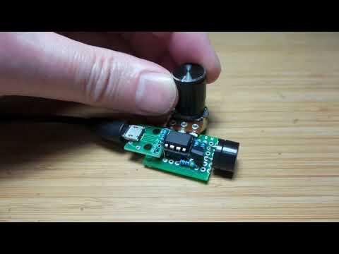
The ATtiny dispenses with much of the circuit complexity. What remains is just:
- a pull-up enable resistor
- pot for control input
- low-side NPN driver for the speaker output
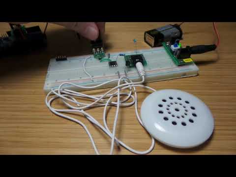
I started with the circuit running from 5V on a breadboard:


Using Original Source
Before going further, I wanted to verify the original source code and see what the behaviour is like with it.
The original source is available from the elektor site. It was written in the BASCOM-AVR language. Since I am on a Mac right now, I’m not setup to recompile the source. I will just use the hex file provided.
The code was originally written for an ATtiny45. I’m using an ATtiny85. this should be fine because I think the main distinction is that the t85 has more memory.
I’m using an Arduino ISP with a DIY programmer shield to program the ATtiny85, details are in the LEAP#070 project.
The Attiny can either be programmed on the shield, or it can be programmed in-circuit (as long as the pot is positioned roughly midway):

Checking the fuses with avrdude:
$ avrdude -c stk500v1 -p attiny85 -P /dev/cu.usbmodem1421 -b 19200 -U lfuse:r:-:i

avrdude: AVR device initialized and ready to accept instructions

Reading | ################################################## | 100% 0.02s

avrdude: Device signature = 0x1e930b (probably t85)
avrdude: reading lfuse memory:

Reading | ################################################## | 100% 0.01s

avrdude: writing output file "<stdout>"
:01000000629D
:00000001FF

avrdude: safemode: Fuses OK (E:FF, H:DF, L:62)

avrdude done.  Thank you.
The engbedded fusecalc site is invaluable for decoding or calculating fuses values. It confirms that E:FF, H:DF, L:62 are factory defaults: 8 MHz internal oscillator with CKDIV8 prescaler: so it is running at 1 MHz.
The original sketch was written to run at 8MHz, i.e. with CKDIV8 diabled for a fuse setting of E:FF, H:DF, L:E2
To change the CKDIV8 from its factory setting, I just need to update the low fuse:
$ avrdude -c stk500v1 -p attiny85 -P /dev/cu.usbmodem1421 -b 19200 -U lfuse:w:0xe2:m

avrdude: AVR device initialized and ready to accept instructions

Reading | ################################################## | 100% 0.03s

avrdude: Device signature = 0x1e930b (probably t85)
avrdude: reading input file "0xe2"
avrdude: writing lfuse (1 bytes):

Writing | ################################################## | 100% 0.02s

avrdude: 1 bytes of lfuse written
avrdude: verifying lfuse memory against 0xe2:
avrdude: load data lfuse data from input file 0xe2:
avrdude: input file 0xe2 contains 1 bytes
avrdude: reading on-chip lfuse data:

Reading | ################################################## | 100% 0.01s

avrdude: verifying ...
avrdude: 1 bytes of lfuse verified

avrdude: safemode: Fuses OK (E:FF, H:DF, L:E2)

avrdude done.  Thank you.
Uploading the original hex file,
with a copy stored locally in original_source/BuheiTiny45.hex:
$ avrdude -v -c stk500v1 -p attiny85 -P /dev/cu.usbmodem1421 -b 19200 -U flash:w:original_source/BuheiTiny45.hex:i

avrdude: Version 6.3, compiled on Sep 21 2018 at 19:09:46
         Copyright (c) 2000-2005 Brian Dean, http://www.bdmicro.com/
         Copyright (c) 2007-2014 Joerg Wunsch

         System wide configuration file is "/usr/local/Cellar/avrdude/6.3_1/etc/avrdude.conf"
         User configuration file is "/Users/paulgallagher/.avrduderc"
         User configuration file does not exist or is not a regular file, skipping

         Using Port                    : /dev/cu.usbmodem1421
         Using Programmer              : stk500v1
         Overriding Baud Rate          : 19200
         AVR Part                      : ATtiny85
         Chip Erase delay              : 4500 us
         PAGEL                         : P00
         BS2                           : P00
         RESET disposition             : possible i/o
         RETRY pulse                   : SCK
         serial program mode           : yes
         parallel program mode         : yes
         Timeout                       : 200
         StabDelay                     : 100
         CmdexeDelay                   : 25
         SyncLoops                     : 32
         ByteDelay                     : 0
         PollIndex                     : 3
         PollValue                     : 0x53
         Memory Detail                 :

                                  Block Poll               Page                       Polled
           Memory Type Mode Delay Size  Indx Paged  Size   Size #Pages MinW  MaxW   ReadBack
           ----------- ---- ----- ----- ---- ------ ------ ---- ------ ----- ----- ---------
           eeprom        65     6     4    0 no        512    4      0  4000  4500 0xff 0xff
           flash         65     6    32    0 yes      8192   64    128  4500  4500 0xff 0xff
           signature      0     0     0    0 no          3    0      0     0     0 0x00 0x00
           lock           0     0     0    0 no          1    0      0  9000  9000 0x00 0x00
           lfuse          0     0     0    0 no          1    0      0  9000  9000 0x00 0x00
           hfuse          0     0     0    0 no          1    0      0  9000  9000 0x00 0x00
           efuse          0     0     0    0 no          1    0      0  9000  9000 0x00 0x00
           calibration    0     0     0    0 no          1    0      0     0     0 0x00 0x00

         Programmer Type : STK500
         Description     : Atmel STK500 Version 1.x firmware
         Hardware Version: 2
         Firmware Version: 1.18
         Topcard         : Unknown
         Vtarget         : 0.0 V
         Varef           : 0.0 V
         Oscillator      : Off
         SCK period      : 0.1 us

avrdude: AVR device initialized and ready to accept instructions

Reading | ################################################## | 100% 0.02s

avrdude: Device signature = 0x1e930b (probably t85)
avrdude: safemode: hfuse reads as DF
avrdude: safemode: efuse reads as FF
avrdude: NOTE: "flash" memory has been specified, an erase cycle will be performed
         To disable this feature, specify the -D option.
avrdude: erasing chip
avrdude: reading input file "original_source/BuheiTiny45.hex"
avrdude: writing flash (1886 bytes):

Writing | ################################################## | 100% 2.71s

avrdude: 1886 bytes of flash written
avrdude: verifying flash memory against original_source/BuheiTiny45.hex:
avrdude: load data flash data from input file original_source/BuheiTiny45.hex:
avrdude: input file original_source/BuheiTiny45.hex contains 1886 bytes
avrdude: reading on-chip flash data:

Reading | ################################################## | 100% 1.35s

avrdude: verifying ...
avrdude: 1886 bytes of flash verified

avrdude: safemode: hfuse reads as DF
avrdude: safemode: efuse reads as FF
avrdude: safemode: Fuses OK (E:FF, H:DF, L:E2)

avrdude done.  Thank you.
The result is quite similar to the original CMOS circuit. Here’s a quick demo of how it behaves:
Understanding the Source
The original source is a little hard to read. The accompanying article helps a bit. Here’s my attempt to understand what’s going on..
Setting up for an attiny45 running at 8MHz:
'BUhei2 Tiny45
'Frequenzerzeugung
$regfile = "attiny45.dat"
$crystal = 8000000
Set the DDRB register to set PORTB.4 (pin 3) for output, initially low.
This is the speaker driver output.
'Pin B.0 wird Ausgang:
Ddrb = &B00010000
'Alles aus:
Portb.4 = 0
This is BASIC, so old habits for short variable names die hard! I’ve annotated each with my understanding of their use:
Dim Preload As Byte  ' starting value for Timer0
Dim F As Word        ' temporary variable used in recalculating the Preload value
Dim Fg As Word       ' target frequency indicator based on the ADC1 input mapped to a range of 200-3269
Dim Fd As Word       ' frequency fator based on the number of timer overflows in a range of 100-1000
Dim Tmax As Single   ' constant: maximum seconds per clock overflow
Dim Tclk As Single   ' constant: seconds per clock tick
Dim H As Single      ' temporary variable for recalculating Preload value
Configure Timer0 with a prescaler of 256 i.e. 31.25kHz,
and I think implicitly an incrementing timer with max value of 255.
Sets up calling the Oszillator subroutine on timer overflow.
Sets Timer0 to an initial value to 100. As far as I can tell from the BASCOM AVR support documentation, this sets the TCNT0 timer register (not the Output Compare Register OCR0A).
So if TCNT0 is preloaded to 100, the overflow will occur after (255-100) clock ticks.
I figure that means each overflow is running at a frequency of about 202Hz.
Since a full cycle audio output requires two interrupts, this corresponds to an 100Hz output.
On Timer0 Oszillator
Config Timer0 = Timer , Prescale = 256
Enable Timer0
Enable Interrupts
Preload = &H64:                                             '100 Hz
Timer0 = Preload
Configures and enabled the ADC input. Used for reading the pot setting from ADC1 (pin 7):
Config Adc = Single , Prescaler = Auto , Reference = Avcc
Start Adc
Initialises constants:
Tclkcalculated as seconds per clock tick, based on clock frequency adjusted by the prescaler, 32µsTmaxis the maximum time per clock overflow 8.192ms
Variables Fg and Fd are iniitalised to 100, but these values are recalculated in the main loop.
'Init
Tclk = 256 / 8000000
Tmax = 256 * Tclk
Fg = 100
Fd = 100
Main loop:
'Hauptprogramm
'F=200-4000
Do
First step reads ADC1 to Fg, then effectively maps to 3*Fg + 200
i.e. ADC range of 0-1023, maps Fg to a range of 200 to 3269
   Fg = Getadc(1)
   H = Fg + 100
   Fg = Fg + H
   Fg = Fg + H
Next, calculates a revised starting value for the timer (Preload).
Since the value Fd comes from the number of overflows, it is the constantly changing value.
The rest of the calculation is directly in proportion to the ADC1 input.
The calculation is a little hard to follow as it reuses the variable H a few times, but is reduces to the following:
It calculates H = 1/(2 * (Fg + Fd)), representing seconds/cycle.
Given that Fg has a range of 200 to 3269, and Fd has a range of 100 to 1000, the limits of this calculation are as follows:
| Fg | Fd | 1/H | H | Audio Frequency |
|---|---|---|---|---|
| 200 | 100 | 600 | 1.667ms | 300Hz |
| 200 | 1000 | 2400 | 0.417ms | 1.3Hz |
| 3269 | 100 | 6738 | 0.148ms | 4.3kHz |
| 3269 | 1000 | 8538 | 0.117ms | 5.87kHz |
H is then subtracted from Tmax, in other words the actual time per cycle varies from Tmax - Hmax to Tmax - Hmin.
For example, when Fg=200 and Fd=100:
- Tmax: 8.192ms
- H: 1.667ms
- Tmax - H: 6.525ms
- Preload: 203
- Timer0 overflow frequency: 601Hz
- Audio out: 300Hz
So when the pot is roughly midpoint, say Fg = 1700, the audio output will repeatedly rise from 2kHz to 3.26kHz.
Bottom line: the base audio frequency is somewhere between 300Hz and 4.3kHz, which then rises by a value of around 1kHz before it gets reset to the start value again.
   F = Fg + Fd
   H = 2 * F
   H = 1 / H
   H = Tmax - H
   H = H / Tclk
   Preload = Int(h)
The final bit of the loop appears to be a NOP.
Has no discernible impact on behaviour since it only sets F and H to values that are never used.
   H = Preload * Tclk
   H = Tmax - H
   H = 0.5 / H
   F = Int(h)
Loop
End
Timer interrupt routine fires on timer overflow, toggles the PB4 output and increments Fd between 100 and 1000. Two interrupts comprise each audio cycle, producing a symmetrical square wave.
Oszillator:
   Timer0 = Preload
   Portb.4 = Not Portb.4
   Incr Fd
   If Fd > 1000 Then Fd = 100
Return
An Arduino/C++ Port
The original program dates back to a time when BASCOM-AVR might have been a reasonable implementation language. But these days, an Arduino sketch would be much more familiar to embedded tinkerers. So let’s re-implement the routine for the Arduino IDE.
The SimpleSoundEffects2.ino sketch is a port of the original algorithm to the standard Arduino C/C++ toolchain, compiled and programmed with the Arduino IDE.
Aside from the obvious language changes, there are two structural changes I’ve made:
- I’m using Timer1 for the audio oscillator instead of Timer0. This is to avoid contention on Timer0, since by defualt the Arduino libraries use Timer0 for standard timing functions such as
millisanddelay - I’ve refactored the core algorithm to simplify the approach and take advantage of some library functions (in particular:
map)
Refactoring the Audio Synthesis Algorithm
The original code essentially does the “long hand” calculation:
- given
Fgis the pot input level in a range of 200 to 3269, andFdis the monotonically rising component from 100 to 1000 - Fg and Fd are combined to product a time value in seconds:
1/(2 * (Fg + Fd)) - this time value is subtracted from the maximum time per timer overflow cycle
- the resulting time is converted back into the equivalent number of timer steps required per cycle given the know processor frequency and timer prescaler
We can however take a more direct approach given the understanding that:
the range of Fg + Fd produces a proportional change in a range of timer steps (somewhere between 0 and 255)
| Fg | Fd | 1/H | H | Tmax - H | TCNT1 Preset |
|---|---|---|---|---|---|
| 200 | 100 | 600 | 1.667ms | 6.5253ms | 203 |
| 200 | 1000 | 2400 | 0.417ms | 7.7753ms | 242 |
| 3269 | 100 | 6738 | 0.148ms | 8.0436ms | 250 |
| 3269 | 1000 | 8538 | 0.117ms | 8.0749ms | 251 |
Conclusion: in the original code, Fg + Fd range of 300-4269 is proportional to a TCNT1 Preset of 203-251.
This can be achieved with two map statements:
uint16_t Fg = map(analogRead(POT_INPUT_PIN), 0, 1023, 200, 3269);
Preset = map(Fg + Fd, 300, 4269, 203,  251);
I experiemented with slight variations. The code in SimpleSoundEffects2.ino corrently uses this approach:
- the pot input is mapped to a
base_periodranging from 203 to 240 - the count of timer overflows -
modulation_period, ranging from 100 to 1000 - modulatesbase_periodto an upper limit of 253 - the resulting value is set as the the TCNT1 preset
Using Piezo Output
A slight modification of the circuit to use a piezo buzzer as the output instead of a speaker:


Testing on a breadboard:

Mini Protoboard Layout
I used the following layout for a more permanent version of the circuit. It uses piezo speaker on a scrap of protoboard, with a micro USB connector for 5V power.
