
#401 pixie
Research the history and variants of the Pixie QRP transceiver, and build a basic Pixie 4.3 kit on 40m.
Notes
Pixie is the name given to a class of QRP transceiver designs that evolved from the Foxx design described by George Burt GM3OXX in summer 1983 edition of SPRAT magazine. The distinguishing feature is the use of the same bipolar device as the transmit PA and the receiver mixer.
There are many versions of the Pixie available. I picked up a kit based on the Pixie 4.3 PCB from a seller on aliexpress. The kit had a product ID of E0991, but that may just be the merchant’s stock code.
The Pixie may be operated on various bands, but most kits (like the one I’m using) target 40m.
Kit Details
Specs as listed by the vendor:
- This transceiver kit is a perfect DIY kit for radio amateur.
- The local frequency is fixed at 7.023MHz when transmitting, the local frequency is 7.023-7.026MHz when receiving.
- Increase a DC buzzer on the PCB, it will beep when pressing the button. But you can choose whether to install the buzzer as you want.
- Can be powered by 9V battery(not included) or 9-12V DC power supply.
- PCB Size: 5x5cm / 2x2in
- Output Power: 0.8W(9V power supply) / 1.2W(12V power supply)
- Power Supply: 9V Battery(not included) / 9-12V DC Power Supply
- Antenna: 50ohms,unbalanced(antenna is not included)
- Package Size: 7 9.5 1.5cm / 2.8 3.7 0.6in
- Package Weight: 24g / 0.9oz
- Power supply: 9V-12V (Recommended 9V laminated battery)
- Antenna: 50 ohm, unbalanced
- Frequency range: transmitter local oscillator frequency: 7023kHz; receive local oscillator frequency: about 7023-7026KHz
- Headphones: low-impedance headphones
- Transmit power: 0.8W (using a 9V power supply), 1.2W (12V power supply)
- Suppress spurious (harmonic):-20dB

How the Pixie Works
The South Canadian Amateur Radio Society has published one of the best references for the Pixie at w5nor.org/pixie/. It includes links to some of the best resources available.
The main trick that I had to get my mind around was how this circuit can operate as both transmitter and receiver.
The “key” is to note the effect of the key on R5, C9, W1 and D3.
With key-down:
- R5, C9 and W1 bypassed:
- Q2 acts as a class B power amp for the Colpitts local oscillator
- output to antenna via pi-network filter that results in a roughly sine wave
- effect of W1/D2 trimmer capacitor is removed from the Colpitts oscillator, resulting in a transmit frequency that should be spot on 7.023 MHz
- D3 conducts/routes to ground, which disables the LM386 audio amp completely
With key-up:
- D3 is reverse-biased, enabling the LM386 audio amp
- R5, C9 and W1 all back in circuit:
- The W1/D2 trimmer capacitor allows receive frequency adjustment (7023-7026KHz)
- high resistance of R5 effectively disables Q2 RF amplifier and turns it into a simple mixer as part of a direct conversion receiver
- C9 makes a dead short at RF frequencies. This eliminates f1, f2, and f1+f2, leaving f1-f2 (audio - hopefully!) to pass to the LM386 amplifier
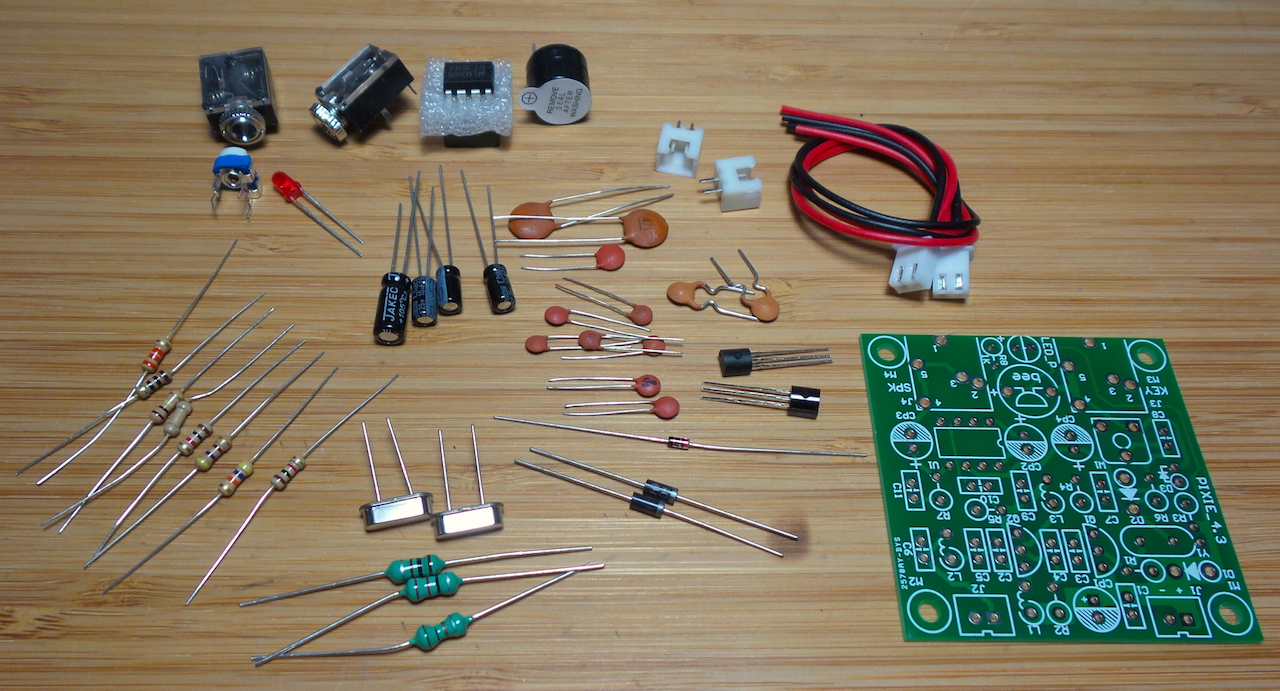
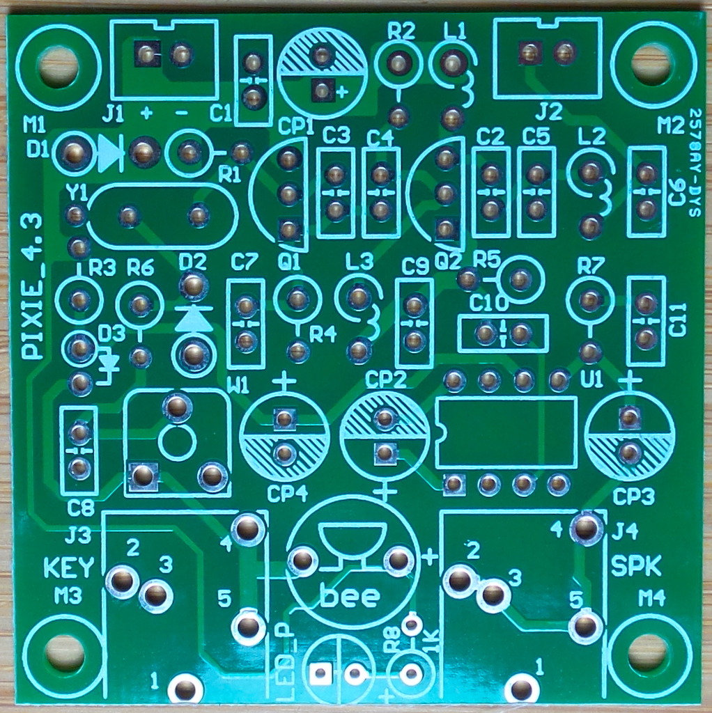
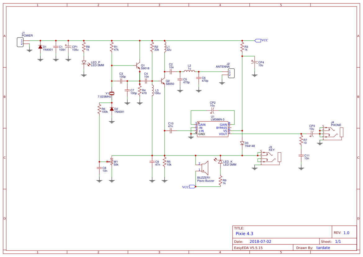
Components and Schematic
The kit I bought did not come with a schematic. The PCB is marked as version “4.3” but I haven’t found a definitive 4.3 schematic, so I traced the PCB and with some reference to other sources I redrew the schematic in EasyEDA.
While it turns out that most components are consistent across versions, the following are the components that most commonly vary. Note:
- the component labels refer to my version of the schematic
- the “As Used” column is the value I am using in this build
- “Other v3/4” refers to various schematics that appear to be v3 or v4 variants
- “Pixie 2” refers to components I’ve seen in Pixie 2 schematics
| Component | As Used | Other v3/4 | Pixie 2 | Notes |
|---|---|---|---|---|
| L2 | 1µH | 1µH | 1.2µH | Some recommend 1µH for 40m and 2.2µH for 80m operation |
| L3 | 100µH | 100µH | 150µH | |
| C2 | 10nF | 100nF | 10nF | |
| C4 | 10nF | 100nF | 82pF | |
| C5 | 470pF | 470pF | 820pF | |
| C6 | 470pF | 470pF | 820pF | |
| C10 | 47nF | 47nF | 100nF |
Modifications
Frequency Agility
A common Pixie modification appears to be one to provide frequency agility so as not to be locked on the crystal frequency. The kit already includes the “trimmer capacitor” modification (comprising D2, R6, C8, W1) that provides some adjustment of diode capacitance.
I haven’t taken this further for now, but have seen some interesting ideas such as vk3ye’s video that covers some crystal and ceramic resonator VXO circuits to add frequency agility.
Side-tone Indicator
The kit included a piezo buzzer side-tone indicator. I did install it, but left the label on the buzzer as everyone knows how annoying they can be!
I did add an LED side-tone indicator (LED_K and R9), which was not in the kit - the LED in the base design is a simple power-on indicator.
High-frequency Bypass
The kit already included a Zobel network on the LM386 output (R7, C11). This is intended to filter high-frequency spikes.
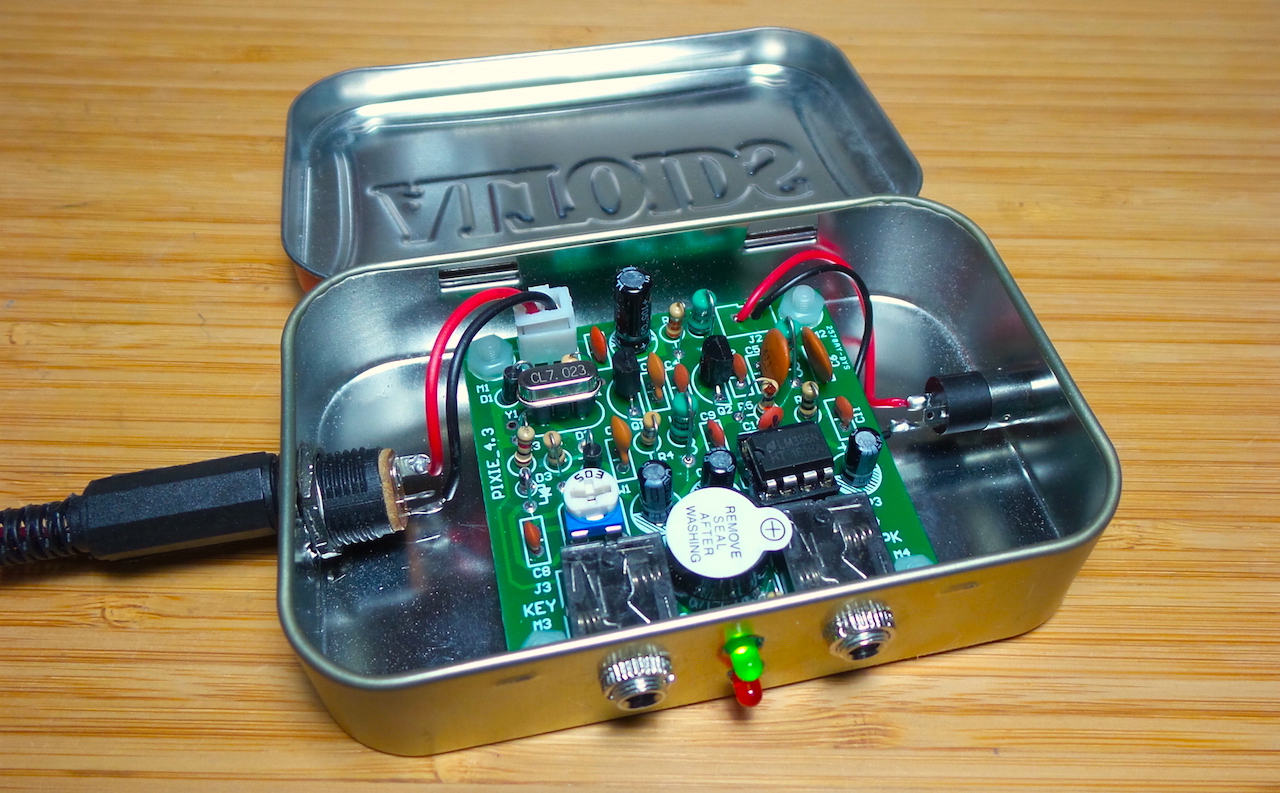
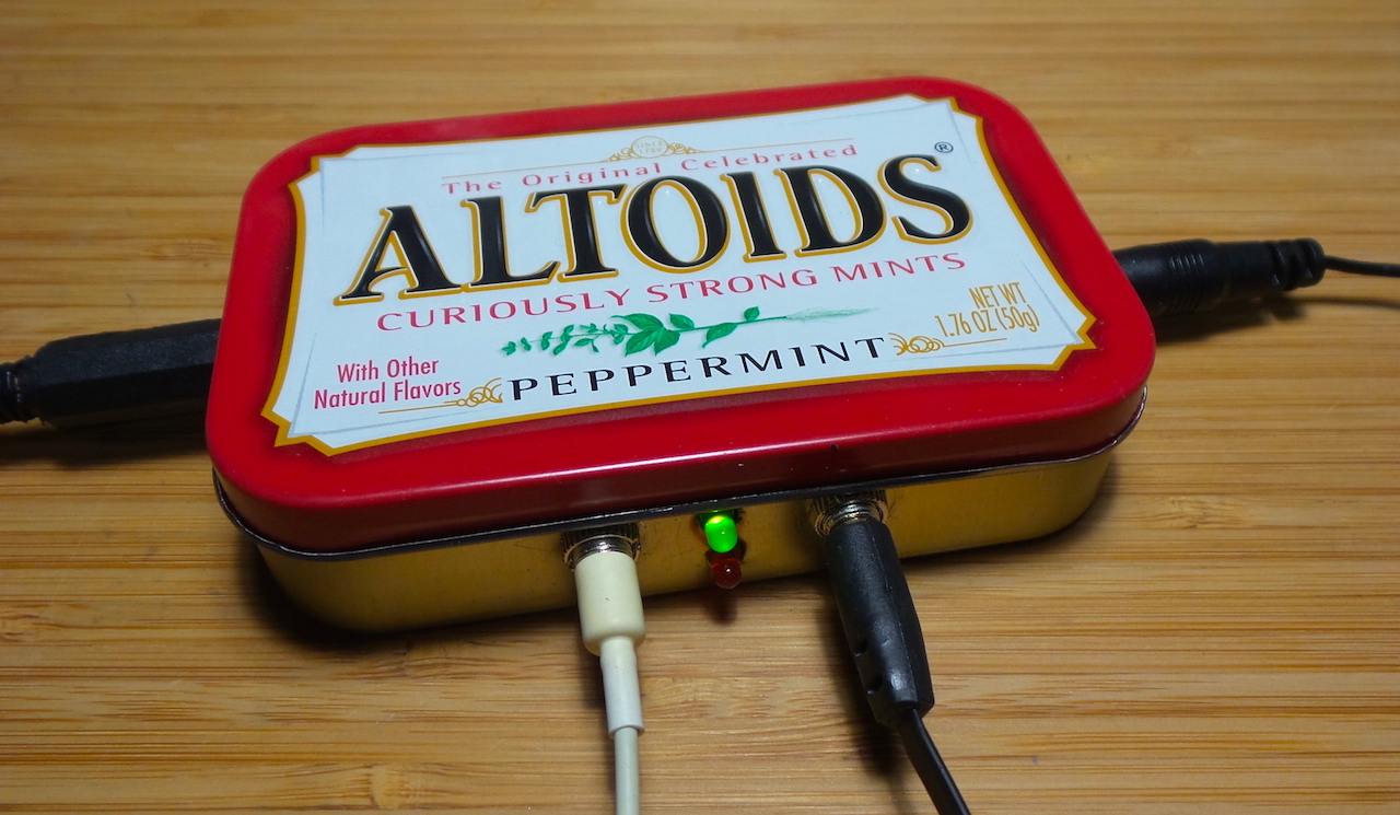
Enclosure
The PCB is a very nice size to fit in an Altoids can;-)
Hooked up for operation:
Operating Results
Not much to report yet - other than it appears to be operating correctly.
Here’s a scope trace of the key-down output into a dummy load:
Credits and References
- my redrawing of the Pixie schematic in EasyEDA
- QRP Pixie Kit CW 40 MeteShortwave Receiver Transmitter 7.023MHz DIY Kits With Buzzer Short-wave Radio Transmitter Receiver
- Similar Pixie Kit on banggood with an excellent PDF manual here
- The SPRAT Pixie File (PDF) - most excellent coverage of Pixie history and variants
- Pixie 1/2 Watt CW 40 Meter Transceiver Kit - one of the best write-ups; from the South Canadian Amateur Radio Society
- Project: 7.023Mhz PIXIE_4.1 QRP CW Transceiver Kit - great write up of a similar Pixie build by lui_gough