
#119 Rotary Encoder Module
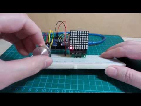
Testing a Rotary Encoder module controlling an LED 8x8 display with an Arduino.
Here’s a quick video of the circuit in action:
Notes
In the RotaryEncoderMethods project I determined that the Rotary library was by far the best option for reading a rotary encoder.
This project is similar, but uses a rotary encoder “module” that includes switch functionality.
The module I am using is the “Rotary Encoder Module for Arduino Dropshipping” (aliexpress seller listing) purchased for US$1.03 (Jul-2015).
The module has built-in 10kΩ pull-up resistors on the signal lines, and external connections as follows:
| Label | Use |
|---|---|
| CLK | Trigger rotational read on falling edge |
| DT(DAT) | When CLK triggered, DT pulled low for counter-clockwise, DT pulled high for clockwise |
| SW | Switch output - pulls the output low when pressed |
| + | Upper supply rail (5V) |
| GND | Ground |
Note the CLK/DT nomenclature is just a simplification of the underlying workings of the rotary encoder. These pins are actually just the regular two quadrature output phases of the encoder. Treating one as a clock and the other as the direction indicator is a workable analogy though.
This sketch uses the rotary encoder to control the position of a single enabled LED on an 8x8 LED display. This makes the accuracy of encoder input quite obvious, as it is very easy to single-step the LED position backwards and forwards.
The rotary encoder module includes a switch (press on the encoder shaft). This is hooked up to clear/reset the display.
Construction
Designed with Fritzing: see RotaryEncoderModule.fzz.


The Sketch
Credits and References
- “Rotary Encoder Module for Arduino Dropshipping” (aliexpress seller listing)
- Purchased for US$1.03 (Jul-2015)
- No longer available from this seller
- RotaryEncoderMethods - a project to test/find the best method for reading a mini rotary encoder
- Rotary_encoder - wikipedia page