#367 nRF24 Scanner
A 2.4GHz channel scanner for the nRF24l01+ with Nokia 5110 LCD display.

Notes
I’m trying to improve the range of nRF24L01+ some modules, and searching around for advice such as the post on fixing your cheap nrf24l01+ pa/lna module.
One thing to check of course is channel congestion.
The nRF24L01+ can operate on a centre frequency from 2.400GHz to 2.525GHz in 1MHz increments. Bandwidth is less than 1MHz at 250kbps and 1Mbps, and less than 2MHz at 2Mbps.
The RF channel frequency is set by the RF_CH register: F0 = 2400 + RF_CH [MHz].
The RF24 library uses channel 76 (2.476GHz) at 1Mbps by default.
The RF24 library comes with a scanner example, which I used as the basic inspiration for this project.
I’ve modified the code somewhat and added a Nokia5110-type display.
Power
The Arduino Uno is only rated to provide 50mA on the 3.3V rail, so I have added a separate supply using an AMS1117-3.3.
Nokia 5110 LCD Configuration
The Nokia 5110 LCD I have uses an SPI interface. I tried unsuccessfully to get the nRF24 and LCD modules to play nicely together with hardware SPI. In the end I gave up and switched to software SPI for the LCD display (using the Adafruit PCD8544 library), and hardware SPI for the nRF42.
The Nokia 5110 screen is a 48 × 84 pixels matrix LCD, driven by the Philips PCD8544.
Module Connections
Here’s the mapping from the terminology used by the 5110 and nRF24 modules and pins on an Arduino Uno.
| Module | Pin | Usage | Arduino Uno |
|---|---|---|---|
| 5110 | DC/CSN | address line 0 | 3 |
| 5110 | CE/SCE/SS | chip enable | 4 |
| 5110 | RST | reset | 5 |
| 5110 | DIN | data in | 6 |
| 5110 | CLK | clock | 7 |
| 5110 | VCC | power | 5V |
| 5110 | BL | Backlight on when GND | |
| 5110 | GND | Ground | GND |
| nRF24 | GND | Ground | GND |
| nRF24 | 3V3 | 3.3V supply | |
| nRF24 | CE | chip enable | 8 |
| nRF24 | CSN | 9 | |
| nRF24 | MOSI | data in | 11 SPI MOSI |
| nRF24 | MISO | data out | 12 SPI MISO |
| nRF24 | SCK | clock | 13 SPI SCK |
Scanner Sketch
The Scanner program is an extension of the RF24 scanner example. It shows the channels that present a carrier.
It currently supports two modes:
current- displays the latest samplecumulative- displays counts since last reset
It is pretty basic, and the display is a bit cramped to fit on the LCD display. Some improvement ideas:
- make the mode switch more instantaneous (currently only takes effect after the current scan is complete)
- add a waterfall mode
- add a histogram mode
- zoom in to see individual channels in more detail
Breadboard Construction
Tested first on a breadboard:


Packaged Module Build
I decided to package the project in an enclosure:
- with 5v and 3.3v supply rails
- reverse polarity protection
- it uses external power without a power switch. There probably is room to fit a 9V battery in the case, but I haven’t bothered with that right now.
The full schematic for the module is available here in EasyEDA:

I’m using some protoboard, and here’s a sketch of the basic layout:

The finished board:


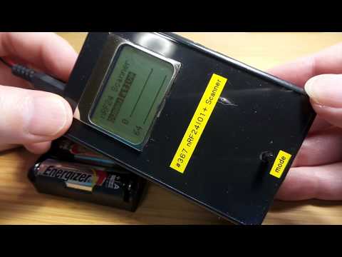
In a plastic enclosure:

Here’s a quick demo..