
#481 TM1638 7-Segment LED Driver
Investigating the capabilities of the TM1638 as a 7-segment display driver and key pad controller.
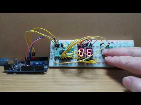
Here’s a quick demo..
Notes
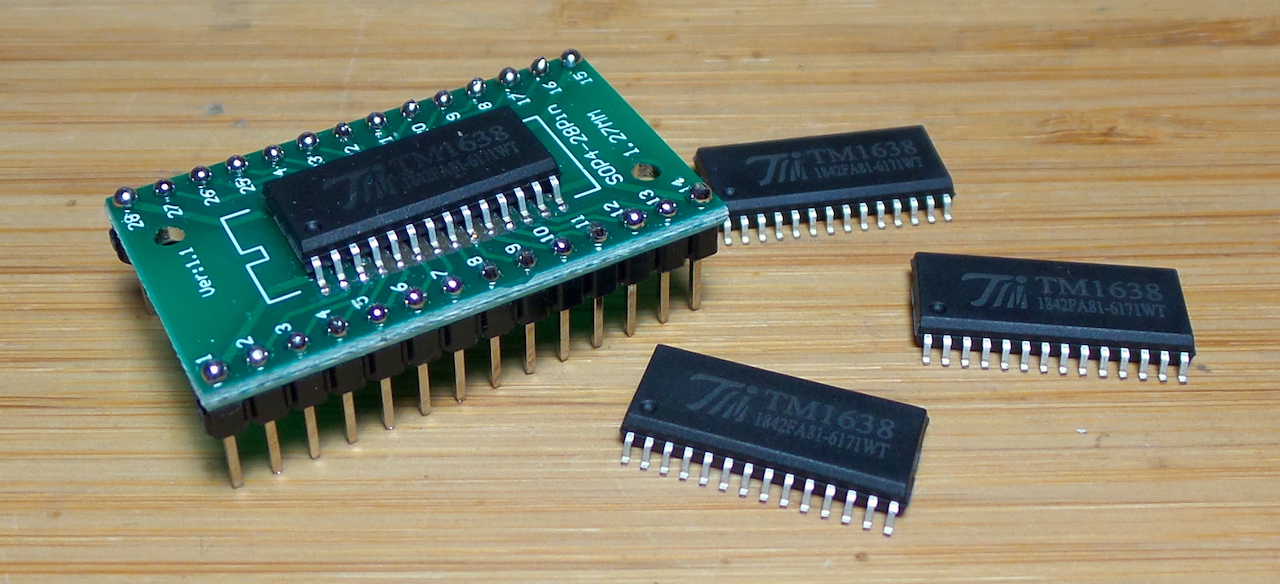
The TM1638 is an LED display driver that is kind of like a souped up version of the MAX7219.
It can handle 10x 7-segments (plus decimal point) and also supports keyboard scanning for up to 24 buttons. It is mainly used for interface control in simple home appliances. There are a number of development modules available that use TM1638, like this example
Unlike the MAX7219, it doesn’t include a fonts or other decoding for display (not that the MAX7219’s capabilities in this area are that great).
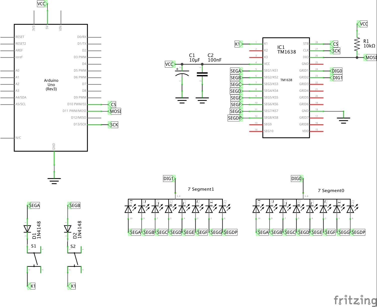
LED 7-Segment Components
The 7-segment components I’m using here are similar to the SC56-11.
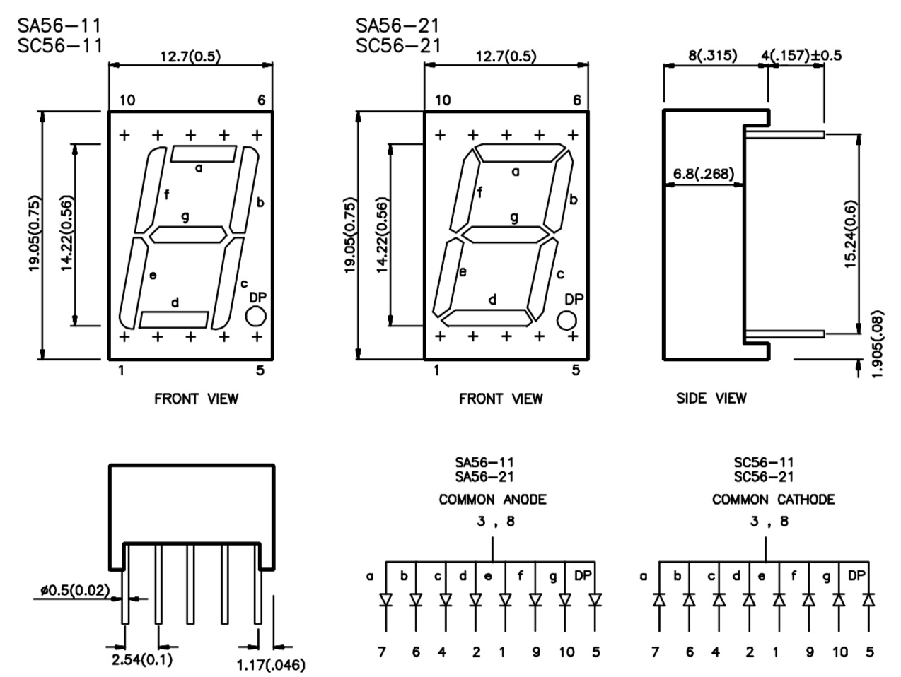
I’m using common cathode variants, so segments are wired to the TM1638 segment pins, and each digits cathode goes to the corresponding grid pin.
| Segment | SC56-11 pin | TM1638 SEG pin |
|---|---|---|
| a | 7 | SEG1: 5 |
| b | 6 | SEG2: 6 |
| c | 4 | SEG3: 7 |
| d | 2 | SEG4: 8 |
| e | 1 | SEG5: 9 |
| f | 9 | SEG6: 10 |
| g | 10 | SEG7: 11 |
| dp | 5 | SEG8: 12 |
Pushbutton Inputs
In a bit of smart multiplexing, the TM1638 also supports an array of push-buttons. These are connected from the segment pins (the same segment pins driving the LED displays) to one of the X1, X2 or X3 pins. thus a maximum of 8 segments x 3 X? pins = 24 buttons.
Putting a diode in series with each button allows combinations of keypresses to be correctly detected.
Display Address
Each grid has 16 bits of of memory, divided into two byte-size memory locations, to specify the on/off values for the 8 segments (plus 6 unused bits).
Even addresses contain bits for Seg1-8:
| Seg1 | Seg2 | Seg3 | Seg4 | Seg5 | Seg6 | Seg7 | Seg8 |
|---|---|---|---|---|---|---|---|
| B0 | B1 | B2 | B3 | B4 | B5 | B6 | B7 |
Odd addresses contain bits for Seg9-10:
| Seg9 | Seg10 | x | x | x | x | x | x |
|---|---|---|---|---|---|---|---|
| B0 | B1 | B2 | B3 | B4 | B5 | B6 | B7 |
The grids are addressed sequentially as follows:
| Grid | Even | Odd |
|---|---|---|
| 1 | 0x00 | 0x01 |
| 2 | 0x02 | 0x03 |
| 3 | 0x04 | 0x05 |
| 4 | 0x06 | 0x07 |
| 5 | 0x08 | 0x08 |
| 6 | 0x0A | 0x0B |
| 7 | 0x0C | 0x0D |
| 8 | 0x0E | 0x0F |
Incremental Addressing Mode
Setting incremental addressing mode allows all or a series of register addresses to be written in a continuous stream of data.
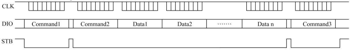
Sequence:
- Command(1):
0b01000000: sets auto incrementing write mode0b01xxxxxx- data command mode0bxxxx0xxx- normal mode0bxxxxx0xx- auto increment0bxxxxxx00- write mode
- Command(2):
0b11000000: sets starting display address0b11xxxxxx- set address mode0bxxxx0000- set address 0x00
- Data(1) - Data(n): register values
- Command(3):
0b10001111: sets display control0b10xxxxxx- set display control mode0bxxxx1xxx- set display on0bxxxxx111- set full brightness
Correct sequencing of the chip select (STB) line state is critical for the command to be accepted.
Fixed Addressing Mode
The fixed address mode allows individual display register values to be updated.
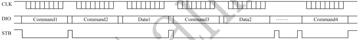
Sequence:
- Command(1):
0b01000100: sets auto incrementing write mode0b01xxxxxx- data command mode0bxxxx0xxx- normal mode0bxxxxx1xx- fixed addressing0bxxxxxx00- write mode
- Command(2):
0b11000000: sets display address0b11xxxxxx- set address mode0bxxxx0000- set address 0x00
- Data(1): value to set to register 0x00
- Address command & value bytes repeat for as many addresses as required
- Command(3):
0b10001011: sets display control0b10xxxxxx- set display control mode0bxxxx1xxx- set display on0bxxxxx011- set brightness to 10/16ths
Correct sequencing of the chip select (STB) line state is critical for the command to be accepted.
Reading Push-buttons
Keypad data is read in through the data connection after putting the TM1638 into read mode. The chip handles multiplexing the display so that reading key values does not interfere with the LED display (smart!).
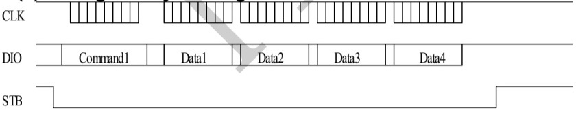
Sequence:
- Command(1):
0b01000010: sets read mode0b01xxxxxx- data command mode0bxxxx0xxx- normal mode0bxxxxxx10- read mode
- Data(1-4): 4 bytes of key scan data
Keypad data is read as 4 bytes, containing all the values for the matrix of the 8 segments x 3 key grids.
| Bit: | B0 | B1 | B2 | B3 | B4 | B5 | B6 | B7 |
|---|---|---|---|---|---|---|---|---|
| Byte1 | K3.KS1 | K2.KS1 | K1.KS1 | X | K3.KS2 | K2.KS2 | K1.KS2 | X |
| Byte2 | K3.KS3 | K2.KS3 | K1.KS3 | X | K3.KS4 | K2.KS4 | K1.KS4 | X |
| Byte3 | K3.KS5 | K2.KS5 | K1.KS5 | X | K3.KS6 | K2.KS6 | K1.KS6 | X |
| Byte4 | K3.KS7 | K2.KS7 | K1.KS7 | X | K3.KS8 | K2.KS8 | K1.KS8 | X |
For example, the two buttons I have installed for the demo connect grid K1 to KS1 (seg1) and KS2 (seg2) respectively:
| K1 | K2 | K3 | |
|---|---|---|---|
| KS1 | button 1 | ||
| KS2 | button 2 | ||
| KS3 | |||
| etc |
Thus:
- when the first is pressed, byte1 =
0b00000100 - when the second is pressed, byte1 =
0b01000000 - when both are pressed, byte1 =
0b01000100
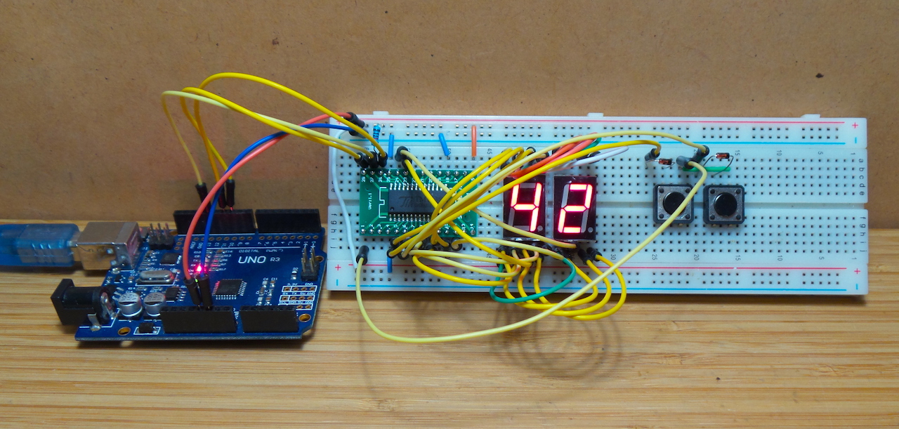
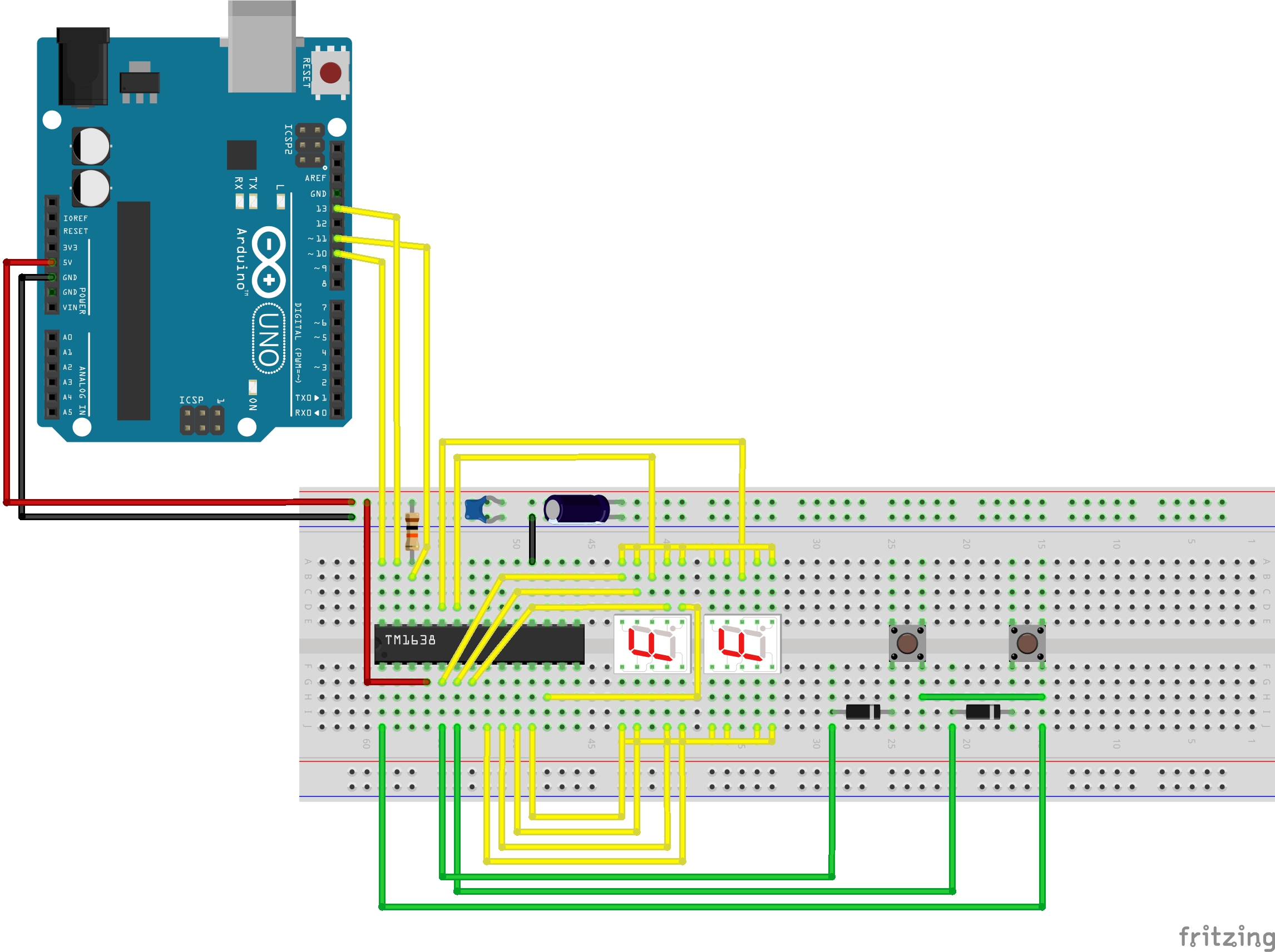
Construction
For the purposes of a simple demonstration, I’m using 2x 7-segment LED displays and 2x push-buttons on a breadboard.
Outgoing, the TM1638’s DIO pin is an open drain and therefore requires a pull-up.
Example Code
The RawDrive.ino sketch is an example of how to drive the TM1638 directly with software serial control - actually, the standard
shiftOut and shiftIn functions proved quite sufficient.
It provides an example of all the main modes of interaction:
- after start up, it runs an automatic sequential counter using Fixed Address Mode
- simultaneous keypress will:
- clear the display, using incremental address mode
- switch to manual counter mode
- In manual count mode:
- press one button decrements the count using Fixed Address Mode
- press the other button increments the count using Fixed Address Mode
- simultaneous buttons clears and goes back to automatic sequential counter mode
I’ve split the code into a couple of classes:
TM1638Driveris responsible for all communications with the TM1638KeyControllerencapsulates the logic for interpreting key scan data
The main loop processes with the manual or automatic incrementing modes.
Rather than handle that with a bundle of if-then-else statements, I’ve implemented the two operations as separate functions
(manualStrategy and automaticStrategy). Switching modes simply swaps the function that is called on each loop.
Credits and References
- Titam TM1638 - info from the original manufacturer, Shenzhen Titan Micro Electronics Co., Ltd. (深圳市天微电子股份有限公司)
- TM1638 Tutorials - Elettronica
- tm1638-library
- Example module using the TM1638
shiftInshiftOut