
#128 ATtiny TotalSleep
Test a total power shutdown with an ATtiny85 processor on a breadboard: power-on with push-button PFET; power-off by the microprocessor itself.
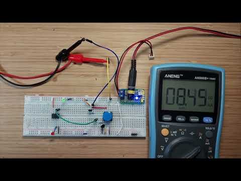
Here’s a quick video of the circuit in action:
Notes
The ATtiny SleepMode project showed me that even in CPU sleep mode, an ATtiny85 circuit can still draw something in the order of 238µA.
This project tests a scheme for total power shutdown triggered by the microcontroller itself. The circuit then draws virtually no current (just component leakage).
The trade-off is that the circuit requires an external trigger to wake-up again. Here it uses a push-button to switch a p-channel MOSFET.
How it Works
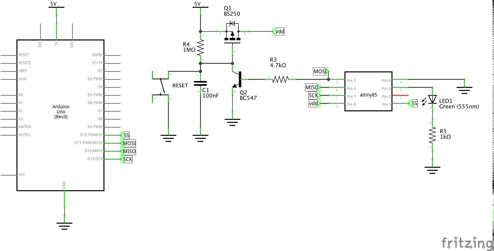
- power is supplied to the ATtiny and other circuit elements through a p-channel MOSFET (I’m using a BS250 here)
- when power is turned on, the 1MΩ resistor R1 charges the 220nF capacitor C1 with a time constant of 220ms
- this keeps the FET Vgs negative long enough for the ATtiny to power up and apply a high signal to the base of the NPN transistor
- ATtiny85 cold power-on is typically up to ~65 ms with default fuses.
- With optimized fuses (fast startup), startup may only take a few microseconds to a few milliseconds
- the NPN collector-emitter conduction holds the FET Vgs negative, and therefore “powered on”
- when the ATtiny wants to power-down, it brings the NPN base low, cutting the collector-emitter channel, and sending the FET Vgs to 0V.
- this turns off the FET and everything is powered down. The current drawn in this state is limited to leakage of the components
- to power-up, the push-button shorts the capacitor, bringing the FET Vgs down and setting the cycle off again
Circuit Design
Designed with Fritzing: see TotalSleep.fzz.
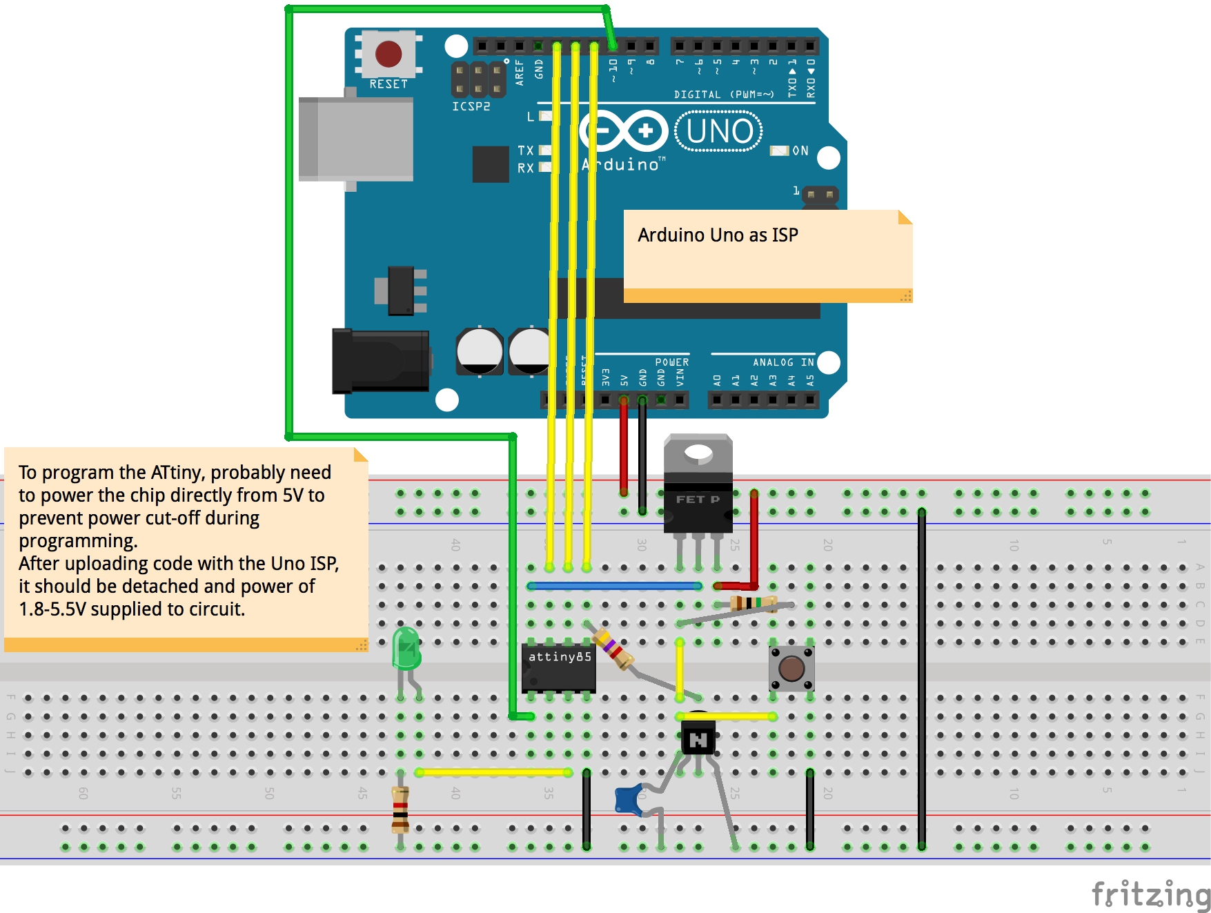
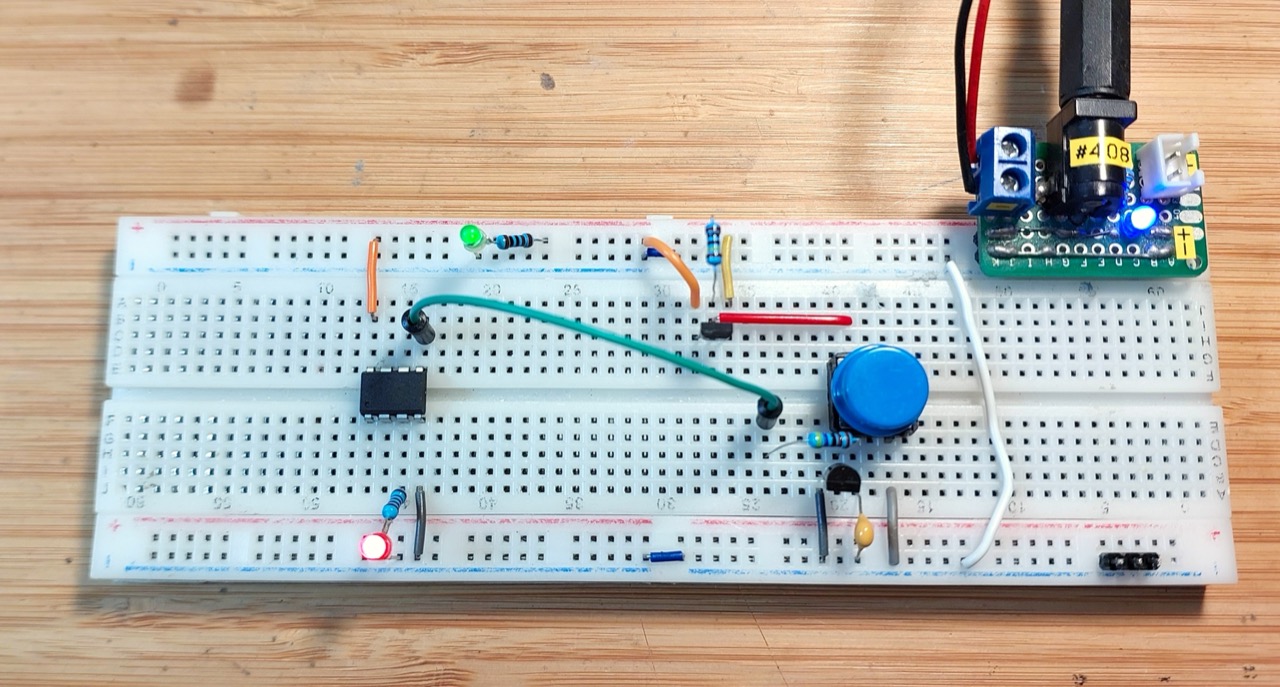
Setup on a breadboard:
The Sketch
See TotalSleep.ino. Essential program structure:
- setup:
- pulls the
POWER_ENpin high
- pulls the
- main program:
- flashes the LED at 5Hz for 2 seconds
- trigger power-off: switch the
POWER_ENpin to high-impedance input state - NOP until dead
The ATtiny85 is programmed using an Arduino Uno as described in LEAP#070 Programming an ATtiny With ArduinoISP.
Demonstration
This all seems to work very reliably. The following scope trace illustrates the behaviour:
- CH1 (Yellow): 5V power
- CH2 (Blue): VDD
- CH3 (Red):
POWER_ENpin - CH4 (Green): R1-C1 junction
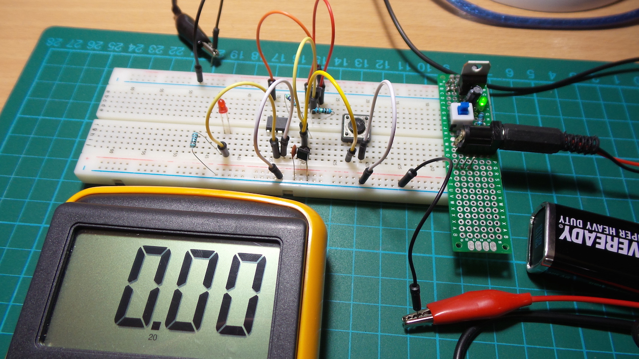
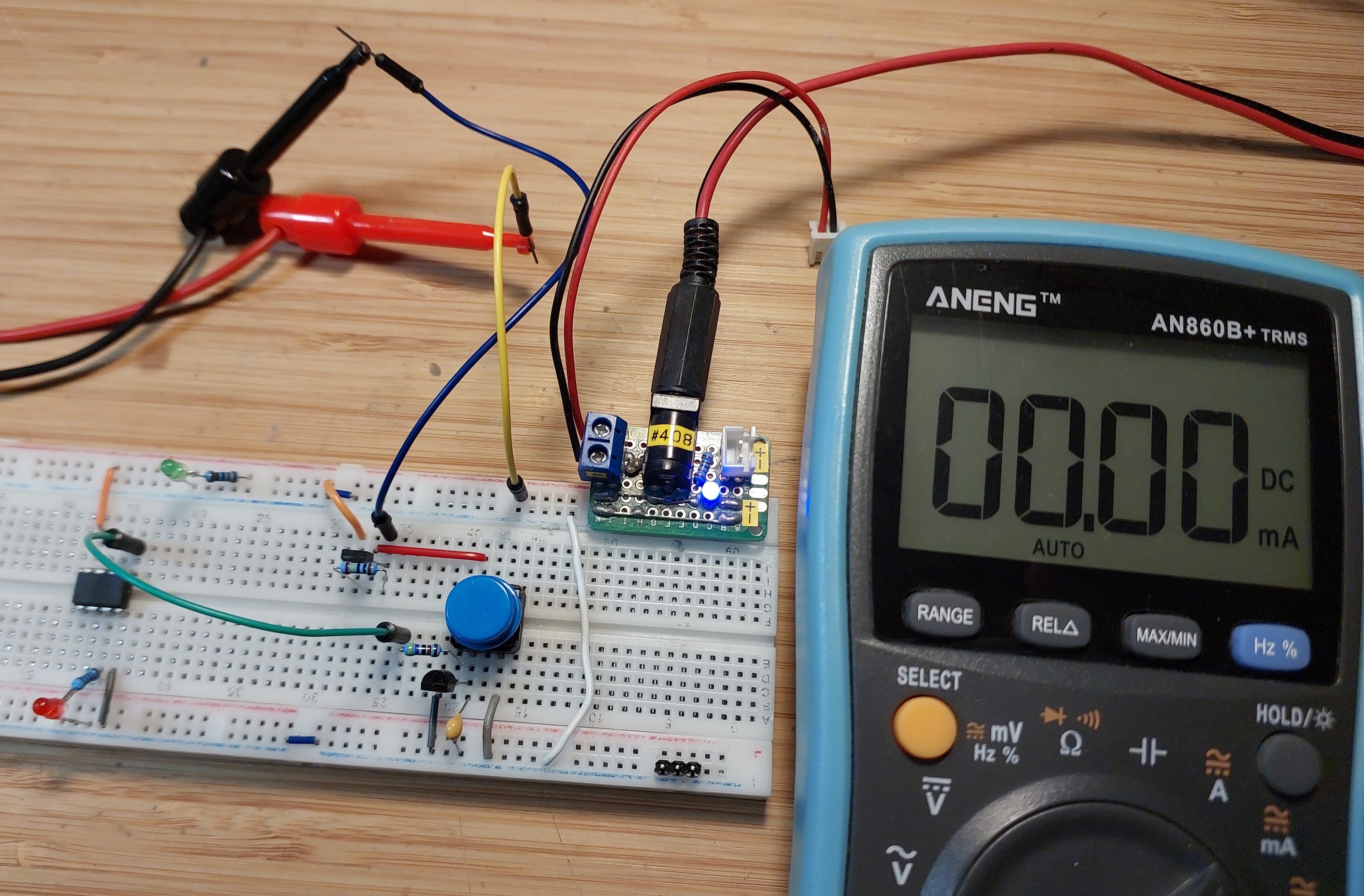
After the ATtiny85 cuts its power, total current draw is negligible, less than the 1µA resolution of an inline multimeter:
Here’s a quick video of the circuit in action:
Credits and References
- LEAP#070 Programming an ATtiny With ArduinoISP
- ATtiny85 datasheet
- BS250 datasheet
- BC547 datasheet
- Arduino DigitalPins reference
- Topic: Circuit for MCU to control its own power on/off - another approach using a flip-flop
- Self Shutting Down Arduino - describes a similar approach