
#587 RGB Auto-ranging Ohmmeter
An auto-ranging ohmmeter that uses an LCD and RGB LEDs to display the best-matched E24 standard resistor color code for the measured resistance.

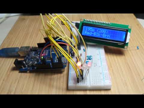
Here’s a quick demo..
Notes
I saw an interesting circuit in Silicon Chip 2021-03 (p41): Displaying digits using single RGB LEDs by Benabadji Mohammed Salim, Oran, Algeria. It demonstrated how to use small PICs to drive RGB LEDs to mimic resistor color coding.
I like this kind of idea - ingenious, but not very practical - and it inspired me to do something similar. I’ve taken the basic idea run with it..
This project is a Ohmmeter featuring:
- Arduino Uno (ATmega328P) processor
- auto-ranging ohmmeter from ~55Ω through to <400kΩ.
- LCD display of:
- measure resistance
- closest E24 standard value
- 3 band color code names
- and of course: RGD LED display of the color codes
Conclusion: the ohmmeter works pretty well, but the RGB LEDs are a little unconvincing for some colors. I may make a PCB just for kicks to present this a little better..
Method of Resistance Measurement
The test circuit puts a known resistor in series with the unknown resistor, and a voltage measurement taken at their junction.
Specifically the circuit is: VCC -> R1 (known resistor) > measurement point (Vx) -> Rx (unknown resistor) -> ground.
This comprises a voltage divider:
Vx = VCC * Rx/(R1 + Rx)
And the unknown resistance can be calculated using Ohms Law:
- Given:
Rx = Vx/I - And:
I = (VCC - Vx)/R1 - Therefore:
Rx = Vx * R1/(VCC - Vx)
Auto-ranging
The Arduino’s ATmega328P uses an integrated 10-bit analog to digital converter, producing integer output ranged from 0 and 1023. With the default 5V reference, this means a resolution of only 4.883 mV.
As such, the value of “known” resistor in the voltage divider is quite important to keep readings within useful range. Best result is when the known and unknown resistors are similar in size.
So to cover a decent resistance range, the circuit “auto-ranges”… basically switching in different known resistors to find the most suitable. In this circuit, I’ve included 4 known resistor options (220Ω, 1kΩ, 10kΩ, 100kΩ) to allow an effective range from ~55Ω through to <400kΩ.
- higher resistances (e.g. up to 10MΩ) could be covered by adding another resistance option - but I had to stop at some point!
- 220Ω is about the lowest I could safely go without adding some over-current protection complexity i.e. consider a full short - 23mA is already getting close to the 40mA max rating for GPIO pins on the ATmega328P.
The auto-ranging works by:
- starting from largest known resistor value, working down to smallest
- the selected resistor GPIO pin is enabled (all others are kept in high-impedance input mode so they do not affect the reading)
- the resulting voltage at the measurement point (Vx) is read through an analog pin
- if Vx is between 1V and 4V (not too high, not too low), this becomes the official result
- else skip to next smallest resistor and repeat
The result of that process will either result in a valid reading using one of the known resistors, else no result - meaning the unknown resistance is either:
Common Standard Resistor Values
Once a resistance reading has been made, the code uses a fairly brute-force method to find the “closest” standard resistance value from the E24 values (5% tolerance) series: 1.0, 1.1, 1.2, 1.3, 1.5, 1.6, 1.8, 2.0, 2.2, 2.4, 2.7, 3.0, 3.3, 3.6, 3.9, 4.3, 4.7, 5.1, 5.6, 6.2, 6.8, 7.5, 8.2, 9.1.
RGB Display
Once the standard resistor value has been calculated, it is represented with a 3-band display:
- on the LCD in words
- on the 3 RGB LEDs as “approximations” of the correct color!
The 3 RGB LED outputs are multiplexed so only 6 pins are required:
- 3 pins to provide the red, green and blue PWM signals for a specific position
- 3 pins to enable one of the 3 LEDs in a fast round-robbin sequence
To allow a relatively flicker-free display whil not interferring with the resistance measurement, the RGB LED multiplexing is handled by a timer interrupt. The interrupt using Timer2. I was concerned this may affect the PWM functions on pin 11, but it seems to coexist quite happily.
Resistor Color Codes
The display is based on the 4-band standard, but with band 4 ignored as that can’t be accurately inferred from the readings.
| band 1 | band 2 | band 3 | band 4 |
|---|---|---|---|
| 1st significant digit | 2nd significant digit | multiplier | tolerance |
Standard Color Codes for Significant Digits
The following table summarises for each color:
- the value it represents when used as a significant digit
- the value it represents when used as a multiplier
- the RGB duty cycle used to generate the color
| Color | Significant Digits Value | Multiplier | RGB Duty Cycle |
|---|---|---|---|
| Black | 0 | x1 | 0 - 0 - 0 |
| Brown | 1 | x10 | 22 - 8 - 0 |
| Red | 2 | x100 | 255 - 0 - 0 |
| Orange | 3 | x1000 | 141 - 13 - 0 |
| Yellow | 4 | x10000 | 255 - 252 - 0 |
| Green | 5 | x100000 | 0 - 255 - 0 |
| Blue | 6 | x1000000 | 0 - 0 - 255 |
| Violet | 7 | x10000000 | 255 - 0 - 92 |
| Grey | 8 | x100000000 | 2 - 1 - 0 |
| White | 9 | x1000000000 | 249 - 253 - 250 |
That the RGB duty cycles I have chosen came about with a deal of experimentation. The best values are also affected by the chose current limiting resistors for each color:
- Red: 1.5kΩ
- Green: 1.2kΩ
- Blue: 680Ω
Note that as I am using common-anode RGB LEDs, the duty cycles mentioned above are inverted in code as a PWM “high” level will turn the LED off and vice versa (i.e. active low logic).
Color Codes for tolerance
For completeness, here are the color codes for tolerances, though unused in the application:
| Color | Value |
|---|---|
| Black | N/A |
| Brown | ±1% |
| Red | ±2% |
| Orange | ±3% |
| Yellow | ±4% |
| Green | ±0.5% |
| Blue | ±0.25% |
| Violet | ±0.10% |
| Grey | ±0.05% |
| White | N/A |
| Gold | ±5% |
| Silver | ±10% |
Libraries Used
The program RgbOhmMeter.ino uses a couple of libraries:
- FlexiTimer2 - convenient way of setting up the Timer2 interrupt for RGB multiplexing
- LiquidCrystal_I2C - to drive the particular LCD over I²C
Construction
For the LCD, I’m using an Hitachi HD44780 compatible 1602 (16 column, 2 row) 5V blue screen LCD and a common 1602/2004 I²C LCD Adapter. Often these can be found sold as a pair/single unit.


Credits and References
- OhmMeter using Arduino – with Auto Ranging Feature
- Resistor Color Code Calculator and Chart
- E series of preferred numbers
- Displaying digits using single RGB LEDs - Benabadji Mohammed Salim, Oran, Algeria - Silicon Chip 2021-03, p41
- 1602/2004 I²C LCD Adapter - aliexpress
- LCD1602 LCD monitor 1602 5V blue screen
- RGB LED Common anode - example from an aliexpress seller