
#115 R2RDAC
Test a 16-bit R2R-ladder digital to analog converter with shift register interface.
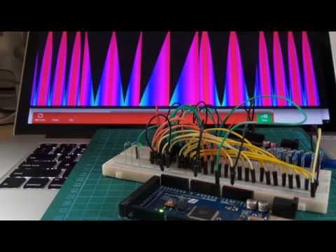
Here’s a quick video of the circuit in action:
Notes
Resistor ladders are a simple and effective technique for digital to analog conversion. I was inspired to experiment with them by w2aew’s video on the basics of R2R Resistor Networks - by far the clearest explanation of the analysis of resistor ladders I’ve seen.
This circuit sets up a 16 bit resistor ladder with 1kΩ as the resistor unit. It demonstrates a few interesting techniques:
- the R2R resistor ladder
- cascaded shift registers
- wave table generation
- data in program memory
- unity gain buffer
Two 74HC595 shift registers are used to drive the ladder. This means the whole thing can be connected to an Arduino using just 3 digital GPIO pins. The latching behaviour of the shift register results in an instantaneous output voltage change, with all inputs to the ladder changing at the same time.
The R2RDAC.ino sketch drives the DAC with a set of sample waveforms: square, sawtooth, sine, and “hump” (rectified sine). It uses standard digitalWrite and shiftOut functions and these are fine at the
relatively low frequencies I’m testing (because I want to be able to see the waves).
To run at higher frequencies, I’d definitely switch to direct port register manipulation.
Here’s a sample trace showing two cycles of each waveform:

The trace was captured with a second Arduino running the PlotNValues sketch. A second arduino was used so that the data capture did not interfere with waveform generation by the first Arduino.
Note: when capturing analogue input across Arduinos, slight differences in reference voltage can skew the results. This can be eliminated by pegging the AREF of one to the AREF of the other. This isn’t so much a concern when reading the buffered output since the peak will be somewhat below the positive power supply (unless a rail-to-rail OpAmp is used).
Output Buffer
It’s possible to tap the voltage output directly from the resistor ladder, however the subsequent circuit will affect the ladder.
An OpAmp unity gain buffer is a simple technique for isolating the output. In this case I’ve used one quarter of an LM324 in unity gain buffer configuration. Note that the output is tapped at the 4.7kΩ/(4.7Ω + 10kΩ) voltage divider point. This is to ensure the voltage extremes from the resistor ladder will fit within the LM324’s output voltage range without clipping.
Wave Table Generation
The demo drives the DAC with a set of sample waveforms: square, sawtooth, sine, and “hump” (rectified sine).
Rather than calculate these on the fly, it uses values from pre-calculated wave tables. This ensures constant-time performance and reduce the processing overhead. To minimise dynamic memory consumption, the tables are loaded in program memory (code space).
The wavetable_generator.rb ruby script is used to generate the wave tables.
Construction


Protoboard Build
I decided to throw the DAC on a protoboard so I have it available as a module for breadboard prototyping. Here’s the finished module:

Here’s the component layout design:

Credits and References
- Resistor ladder - wikipedia
- #85: Basics of R2R Resistor Networks Digital Analog Conversion, Tutorial DAC Thevenin Superposition - another great video by w2aew
- 74HC595 datasheet
- LM324 Datasheet
- List of periodic functions - wikipedia summary of various wave forms
- Arduino Audio Output - R2 Ladder implementation