
#065 LevelIndicatorLM3915
Drive a 10-segment display with a single Arduino pin.

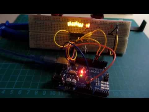
Here’s a quick video of the circuit in action:
Notes
The LM3915 is a 10-segment Dot/Bar Display Driver.
It is primarily intended for audio level indicator applications, as it divides the 10 segments along a log scale of 3 dB/step.
But that doesn’t mean it can’t be used for other purposes. This project is a demonstration of driving the display directly with a single PWM pin.
A second digital pin is used to toggle the dot/bar display mode:
- “dot” mode is where a single element lights to display the peak value
- “bar” mode is where all elements light up in bar-graph fashion
Although when driving the PWM, the dot mode is not particularly useful without further processing of the PWM output to provide a more constant input voltage.
As per the datasheet, there are various ways of setting the voltage reference. Here I’m using R1=1kΩ and R2=1kΩ, which sets the voltage reference at 2.58V.
In effect this means that when input signal reaches 2.58V, that is enough for the final LED to light. NB: according to my multimeter the actual voltage required is 2.53V, no doubt due to small variations in component values within normal tolerances.
Hooking up and Arduino to drive the display with a PWM output requires some smoothing of the output to achieve a stable reference voltage. The C3/R6 RC filter performs this function - at least enough for bar display, but not sufficient for a crisp dot display.
It’s interesting to note that the SIGNAL input draws no current (verified with in-circuit measurement), as according to the datasheet block diagram, the SIGNAL input is used to drive an OpAmp buffer circuit.
Total current drawn by the circuit with all LEDs on is 34.4mA, well within the specs for the Arduino 5V pin, hence why the circuit does not require a dedicated power supply.
LED Current Control
The LM3915 provides LED current-control:
The current drawn out of the reference voltage pin (pin 7) determines LED current. Approximately 10 times this current will be drawn through each lighted LED, and this current will be relatively constant despite supply voltage and temperature changes.
Additional current-limiting resistors may be included to fine-tune the brightness if different colour LEDs are used. Note: the schematic shows 1kΩ current-limiting resistors R3, R4 for the red LEDs. These turned out to not be particularly necessary.
Construction


Credits and References
- LM3915 datasheet
- LEAP#202 Audio Level Indicator Kit - project using the LM3915 in an audio level kit build