
#173 Mini 4x4x4 LED Cube
Driving a mini 63 (4x4x4) LED cube with an Atmel328 and 3 x 74HC595 register interface
Here’s a quick video of the cube in action:
Notes
LED cubes were a “thing” a few years back maybe … but I’ve never built one. Time to fix that…
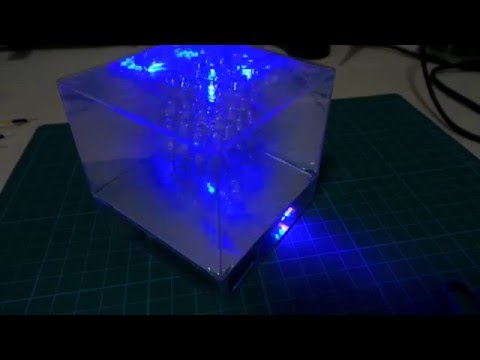
Here’s my “mini” 4x4x4 cube - 3cm per side with 3mm clear blue LEDs. Nice and compact, and delivers nice effects. The clear blue LEDs work really well - very bright, even when driven with minimal current.
It’s encased in a Ferrero Rocher cube box. During the build, that raised some challenges - most of the effort in building the project concerned squeezing all the electronics into the space in the lid (which becomes the base of the cube). Nvm, it all fits and the result it pretty good.
Design Overview
See the schematics for the full details. Here’s how the design breaks down:
- A 9V battery and 7805 linear regulator with some smoothing caps provides a regulated 5V power supply that powers the entire system.
- An ATmega328P microcontroller runs the cube. An in-system programming interface is exposed for updating the code at any time.
- 3 x 74HC595 shift registers are used to latch the instructions to the cube
- LED cathodes are controlled with 2N7000 n-channel MOSFETs
- the LED array uses 16 clear blue 3mm LEDs. Not only are they quite bright with low currents applied, but being clear they effectively “disappear” when off.
To pack this all into the Ferrero Rocher cube, the components are arranged on two boards:
- 4x6cm board provides a foundation for the LED columns. It hosts all the current-limiting resistors for each column.
- 5x7cm board hosts the Atmel, shift registers and FETs
The boards are inter-connected with 20 pins. It would have been nice to use a plug/socket connectors to allow easy disassembly, but in order to save space, I directly connected (soldered) the boards with a set of pins. Since this is not easily reversible, it encourage me to rigorously test everything before final assembly, and it also meant planning the layout was important because I wouldn’t get a second chance to rethink a decision. So I did lots of drawings, practice assembly, and testing circuit sub-modules as they were constructed.
LED Patterns
So far, just a few for demonstration purposes…
The code is organised so that each pattern is in its own (header) file.
Serial-Parallel Interface
So there are 64 LEDs to drive in a 4x4x4 cube - way more than GPIO pins of a typical MCU. I’ll be solving this problem the standard way - using 74HC595 shift registers to drive all the LED controls required with only 3 GPIO pins.
This involves multiplexing the output so we write 16 LEDs in one go, and relies on persistence of vision as the code cycles through the display of 4 layers of 16 LEDs in rapid succession.
I’m using an array of three 74HC595 shift registers to effectively provide a 24-bit serial to parallel latched interface.
- 16 bits drive the LED cube cathodes (16 pillars)
- 4 bits enable the LED anodes (4 layers)
- 4 spare bits that I’m using to drive an additional 4 LED indicators
Clearing the Registers
It’s possible to clear the 595s by toggling the OE and MR pins, but that would require more connections and extra logic. So I do this with software - shift out a full 24-bits worth of 0s to get the 595s to a “known state”.
Choosing current-limiting Resistor values for the LEDs
With a 5V supply and blue LEDs for a forward voltage of 3.0-3.2V, we’ll drop about 2V max across the resistor. Aiming for 10mA LED current, that means a current limiting resistor of about 200Ω.
The “utility” LEDs will however be a selection of red, green and yellow all with a forward voltage around 2V. At 10mA that calls for a resistor more like 300Ω.
That’s the theory at least! But in practice, apparent brightness is more a function of LED construction than current. The clear blue LEDs I have are super bright even at 4mA.
So, perception is what counts! Here are the resistor values I’ve chosen for the the different LEDs to achieve a suitable brightness:
| LED | Vf | Resistor Selection / Notes |
|---|---|---|
| clear blue | 3.1 | 220Ω - bright enough for main cube even with 4 layer multiplexing |
| yellow | 1.9 | 1kΩ - quite bright, but second fiddle to cube LEDs |
| solid blue | 2.8 | 1kΩ - for similar brightness to yellow |
| red | 1.9 | 330Ω - for similar brightness to yellow |
| green | 2.0 | 330Ω - for similar brightness to yellow |
LED Layer Anode Control
Enabling/disabling each layer calls for a transistor switch. I could use NPN BJTs like in Led4Digit7Segment/DoubleShift project, or n-channel MOSFETs like in Led4Digit7Segment/DoubleShiftWithFETs project.
I think I’ll use 2N7000 MOSFETs - no particular reason except simplicity. I’ve put 10kΩ resistors in the gate connection; these are not strictly required expect perhaps to protected the MCU from a current surge in case of a failing FET.
Construction
NB: see the assets folder for more pictures of the build


Breadboard Build Test

Construction Details
Daughter-board Layouts

LED Construction Jig

LED Base Board Construction

Mainboard Construction
