
#478 Raw MAX7219 7-Segment LED Driver
Driving a series of 7-segment LED displays with the MAX7219 and raw SPI commands.

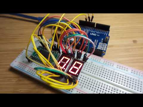
Here’s a quick demo..
Notes
The MAX7219 is a popular serially Interfaced, 8-Digit, LED Display Driver.
It is often used in LED display modules such as this 8 Digit Module from a seller on aliexpress.
The MAX7219 can drive up to 8 common-cathode LED 7-segment units, and can be cascaded to support more digits. The 8x8 outputs can actually be used for any kind of LED display, not just 7-segment displays.
Only one external resistor is required to set the segment current for all LEDs. Current per segment is approximately 100 times the current at pin ISET i.e. ISET is pulled high with an appropriate resistor for the desired current. The current will however also depend on the forward voltage of the LEDs.

MAX7219 Serial Connection
The MAX7219 is connected to the Arduino with three pins as follows. The actual Arduino pin used is not significant, although in this example I have used the conventional SPI pins.
| Connection | Arduino Pin | MAX7219 Pin |
|---|---|---|
| CS | 10 | 12 |
| MOSI/DIN | 11 | 1 |
| SCK/CLK | 13 | 13 |
Scan-Limit Register
The MAX7219 multiplexes the output for up to 8 digits. The scan-limit register sets how many digits are connected, so that the scan can avoid looping through digits that are not conencted.
Decode Mode Register
The MAX7219 allows digits and segments to be addressed individually. This is the “no decode” mode, and requires the host controller to figure out how to draw digits on the LED display.
A “Code-B” mode can be enabled, that allows the digits 0-9 and a small set of characters to be displayed, per the following table. The decimal point is enabled for any of these characters by setting the high bit. Unfortunately, the code set does not include A-F for hexadecimal number display.
| Display | Input Value | Display | Input Value |
|---|---|---|---|
| 0 | 0x00 | 0. | 0x80 |
| 1 | 0x01 | 1. | 0x81 |
| 2 | 0x02 | 2. | 0x82 |
| 3 | 0x03 | 3. | 0x83 |
| 4 | 0x04 | 4. | 0x84 |
| 5 | 0x05 | 5. | 0x85 |
| 6 | 0x06 | 6. | 0x86 |
| 7 | 0x07 | 7. | 0x87 |
| 8 | 0x08 | 8. | 0x88 |
| 9 | 0x09 | 9. | 0x89 |
| - | 0x0A | -. | 0x8A |
| E | 0x0B | E. | 0x8B |
| H | 0x0C | H. | 0x8C |
| L | 0x0D | L. | 0x8D |
| P | 0x0E | P. | 0x8E |
| (blank) | 0x0F | . | 0x8F |
The Decode Mode register is set as follows:
| Behaviour | Set |
|---|---|
| No decode for all digits 0-7 | 0x00 |
| Code-B decode for digit 0 only | 0x01 |
| Code-B decode for digits 0-3 only | 0x0F |
| Code-B decode for all digits 0-7 | 0xFF |
LED 7-Segment Components
The 7-segment components I’m using here are similar to the SC56-11.

| Segment | SC56-11 pin | MAX7219 pin |
|---|---|---|
| a | 7 | 14 |
| b | 6 | 16 |
| c | 4 | 20 |
| d | 2 | 23 |
| e | 1 | 21 |
| f | 9 | 15 |
| g | 10 | 17 |
| dp | 5 | 22 |
Example Code
The RawDrive.ino sketch demonstrates a simple 0.0 to 9.9 counter
using two 7-segment units. It doesn’t use any libraries, just the standard
shiftOut
function to send commands to the MAX7219.
Construction


Credits and References
- SC56-11 Datasheet
- MAX7219 product info and datasheet
- MAX7219 LED Dot Matrix 8 Digit Module - example from a seller on aliexpress
shiftOut