
#255 AvrHardwarePWM/ATtiny
All about hardware PWM with the ATtiny85.

Notes
See the AvrHardwarePWM project for all about hardware PWM with the Arduino UNO/ATmega328.
This project takes the same background and exercises hardware PWM with an ATtiny85 processor.
ATtiny Timers
There are two timers in the ATtiny85 that can be used to generate PWM signals:
- Timer 0 is an 8-bit timer. capable of phase correct and Fast PWM (similar to the ATmega). It is used for functions such as delay() and millis() - these will be affected if PWM frequency is changed.
- Timer 1 is an 8-bit timer, capable of two Fast PWM outputs. It acts as an up-counter, with TOP defined by OCR1C. It also with complementary outputs.
| Compare Register | Timer output | Chip pin | Pin name |
|---|---|---|---|
| OCR0A | OC0A | 5 | PB0 |
| OCR0B | OC0B | 6 | PB1 |
| OCR1A | OC1A | 6 | PB1 |
| OCR1B | OC1B | 3 | PB4 |
| OCR1A | OC1A, complementary output | 5 | PB0 |
| OCR1B | OC1B, complementary output | 2 | PB3 |
NB:
- the chip pin references are for the PDIP/SOIC/TSSOP package.
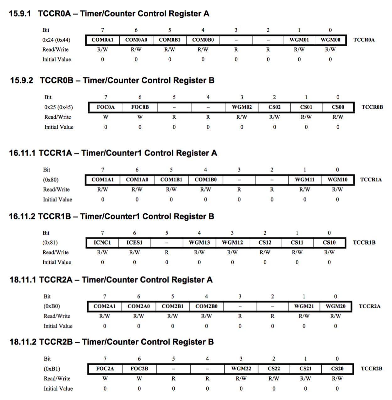
Summary of the Timer-related registers:
How Fast is the Clock?
The ATtiny85 can use an external clock, but by default it uses an internal oscillator. The internal oscillator runs at 8 MHz, prescaled to 1 MHz by default.
The clock settings are in the fuses. I used avrdude to read the fuses:
$ avrdude -c stk500v1 -p attiny85 -P /dev/cu.usbmodem14521 -b 19200 -U lfuse:r:-:i

avrdude: AVR device initialized and ready to accept instructions

Reading | ################################################## | 100% 0.05s

avrdude: Device signature = 0x1e930b (probably t85)
avrdude: reading lfuse memory:

Reading | ################################################## | 100% 0.02s

avrdude: writing output file "<stdout>"
:01000000629D
:00000001FF

avrdude: safemode: Fuses OK (E:FF, H:DF, L:62)

avrdude done.  Thank you.
The engbedded fusecalc site is invaluable for decoding or calculating fuses values.
It confirms that E:FF, H:DF, L:62 are factory defaults: 8 MHz internal oscillator with CKDIV8 prescaler: so it is running at 1 MHz.
Example Sketch
ATtiny.ino exercises the PWM modes, primarily so they can be captured with an oscilloscope. The push-button attached to pin 7 is used to cycle through a few demonstration modes.
The demonstration modes are not exhaustive, but show off most of the PWM capabilities.
I’m using consistent scope connections in all examples:
| Timer output | Chip pin | Pin name | Scope Channel |
|---|---|---|---|
| OC0A | 5 | PB0 | 2 (blue) |
| OC0B | 6 | PB1 | 1 (yellow) |
| OC1A | 6 | PB1 | 1 (yellow) |
| OC1B | 3 | PB4 | 3 (red) |
| OC1A, complementary output | 5 | PB0 | 2 (blue) |
| OC1B, complementary output | 2 | PB3 | 4 (green) |
demoTimer0a: Timer0 Fast PWM
- Fast PWM, TOP=0xFF (WGM01, WGM00)
- Prescaler: 1 (CS00), frequency = 3.906 kHz, Measured: 3.935 kHz
- Outputs:
- PB0 duty cycle = 127/256 = 49.6%
- PB1 duty cycle = 191/256 = 74.6%
- no output on PB3, PB4 (except some crosstalk/noise)
demoTimer0b: Timer0 Phase Correct PWM
- Phase Correct PWM, TOP=0xFF (WGM00)
- Prescaler: 1 (CS00), frequency = 1.961 kHz, Measured: 1.984 kHz
- Outputs:
- PB0 duty cycle = 127/256 = 49.6%
- PB1 duty cycle = 191/256 = 74.6%
- no output on PB3, PB4 (except some crosstalk/noise)
- not the phase correction between the two outputs; start/end of each period is at the top/bottom of the count

demoTimer0c: Timer0 Fast PWM, alternative prescaler
- Fast PWM, TOP=0xFF (WGM01, WGM00)
- Prescaler: 64 (CS01, CS00), frequency = 61 Hz, Measured: 61 Hz
- Outputs:
- PB0 duty cycle = 127/256 = 49.6%
- PB1 duty cycle = 191/256 = 74.6%
- no output on PB3, PB4 (except some crosstalk/noise)

demoTimer1a: Timer1 dual Fast PWM, reduced resolution
- Fast PWM, TOP=0xFF (WGM01, WGM00)
- Prescaler: PCK (CS10), frequency = 7.874 kHz, Measured: 7.905 kHz
- 4-bit counter: OCR1C = 127
- Outputs:
- PB1 (PWM1A); duty cycle = 50/127 = 39.4%
- PB4 (PWM1B); duty cycle = 100/127 = 78.7%
- no output on PB0, PB3 (except some crosstalk/noise)
demoTimer1b: Timer1 dual Fast PWM, complementary outputs
- Fast PWM, TOP=0xFF (WGM01, WGM00)
- Prescaler: PCK (CS10), frequency = 3.906 Hz, Measured: 3.953 kHz
- 8-bit counter: OCR1C = 255
- Complementary outputs enabled (COM1A0, COM1B0)
- Outputs:
- PB1 (PWM1A); duty cycle = 127/256 = 49.6%
- PB0 (COM1A0); complementary; duty cycle = 1 - 127/256 = 50.4%
- PB4 (PWM1B); duty cycle = 100/256 = 39.1%
- PB3 (COM1B0); complementary; duty cycle = 1 - 100/256 = 60.9%
Construction


Credits and References
- LEAP: AvrHardwarePWM - All about hardware PWM with the Arduino UNO/ATmega328
- ATtiny85 datasheet
- ATtiny85 PWM: why does COM1A0 need to be set before PWM B will work?
- engbedded fusecalc
- ..as mentioned on my blog