
#139 Analog Comparator
Testing the Atmega328 built-in analog comparator
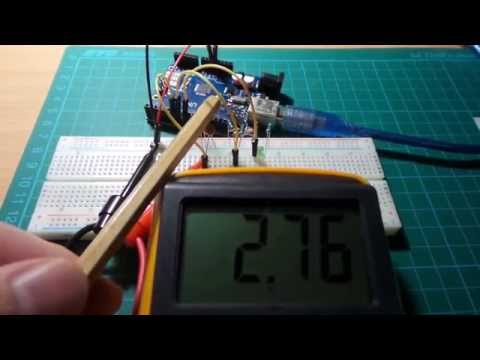
Here’s a quick video of the circuit in action:
Notes
So today I learned (from this question ) that the Atmega328 chip has a built-in analog comparator. That’s neat!
The Analog Comparator is introduced in section 23 of the AVR datasheet:
The Analog Comparator compares the input values on the positive pin AIN0 and negative pin AIN1. When the voltage on the positive pin AIN0 is higher than the voltage on the negative pin AIN1, the Analog Comparator output, ACO, is set. The comparator’s output can be set to trigger the Timer/Counter1 Input Capture function. In addition, the comparator can trigger a separate interrupt, exclusive to the Analog Comparator. The user can select Interrupt triggering on comparator output rise, fall or toggle.
Note that it’s not just the Atmega328 that supports this feature.
The ACSR (Analog Comparator Control and Status Register) determines the behaviour of the Analog Comparator. In the program setup, we:
- disable multiplexed input to the comparator, so AIN1 is used as negative input
- clear any existing comparator interrupts
- enable Analog Comparator interrupts
- select rising-edge interrupt
The code defines an interrupt service routine on ANALOG_COMP_vect.
Now that’s all well and good, but “pin AIN0” and “pin AIN1” sound pretty alien to most Arduino users! A quick check of the ATmega168/328-Arduino Pin Mapping verify:
- Arduino digital pin 6 = AIN0 = pin 12 of the DIP28 chip
- Arduino digital pin 7 = AIN1 = pin 13 of the DIP28 chip
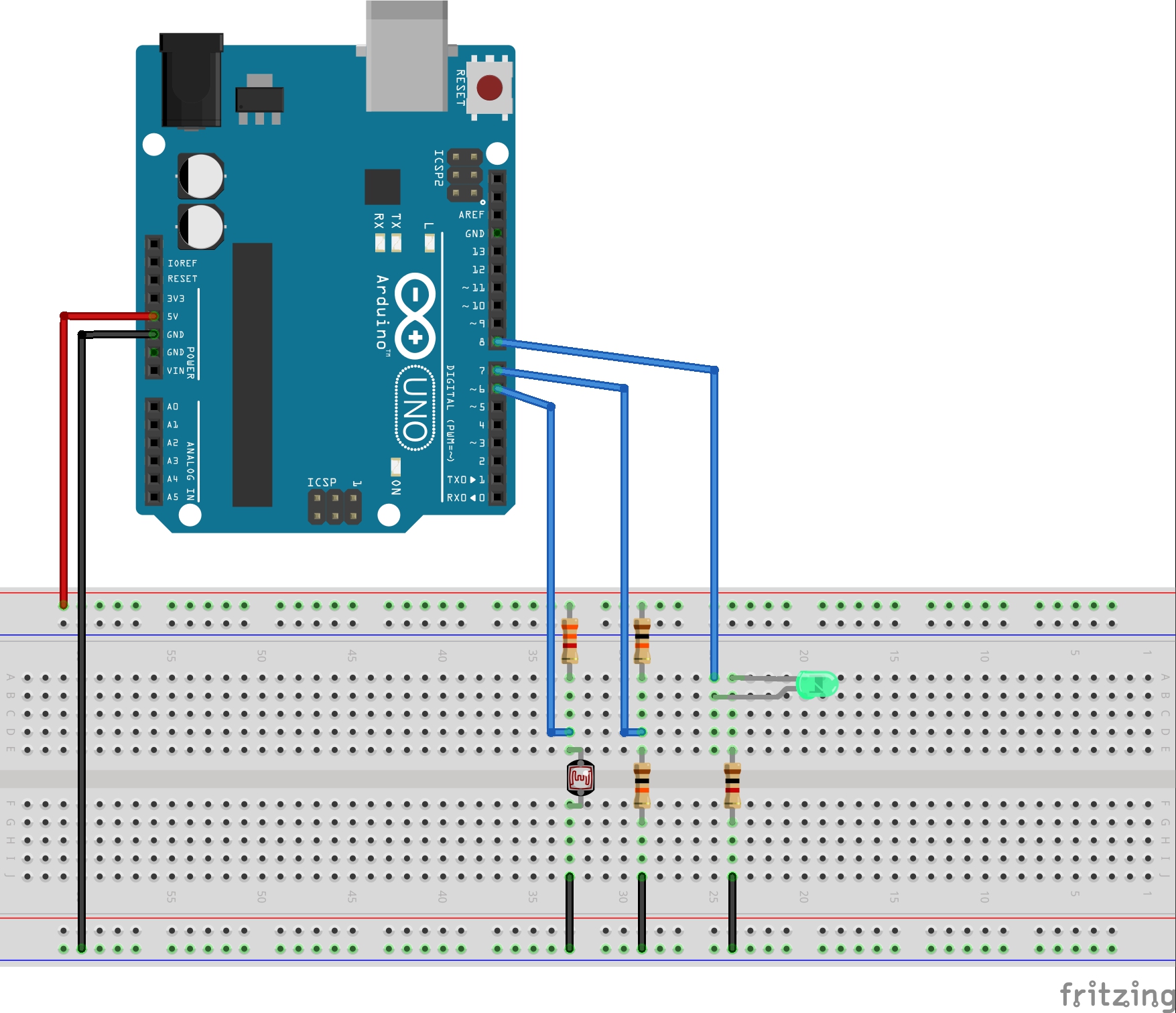
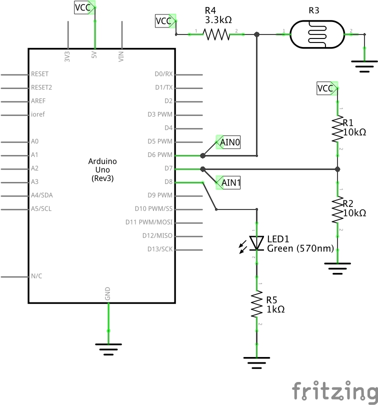
The Test Circuit
This is simple test:
- a voltage divider sets up a ~2.5V reference on AIN1
- an LDR/resistor pair provide a light-dependent voltage input to AIN0
The particular LDR used has a range of about 200Ω (bright light) to 20kΩ (dark). However the ambient light conditions used for testing the circuit exhibits a typical range of 2kΩ-5kΩ, so I’m using a 3.3kΩ as its reference mate.
So the expected behaviour is that we get a comparator threshold rising edge crossing when the LDR goes dark, and a comparator threshold falling edge crossing when the LDR goes light.
Rising, Falling, Change Interrupts?
Setting ACIS1, ACIS0 bits select the interrupt to trigger:
| ACIS1 | ACIS0 | Trigger |
|---|---|---|
| 0 | 0 | Toggle |
| 1 | 0 | Falling |
| 1 | 1 | Rising |
In practice, the comparator can be extremely bouncy. This can cause rising interrupts when only falling are expected, and vice versa. Some measure of debouncing appears to be essential.
So Does it Work?
Yes! The comparator interrupt is excellent, and beats any other approach for speed, processing overhead and lack of external circuitry.
Debouncing is likely essential, unless your application does not care about the number or direction of interrupts raised.
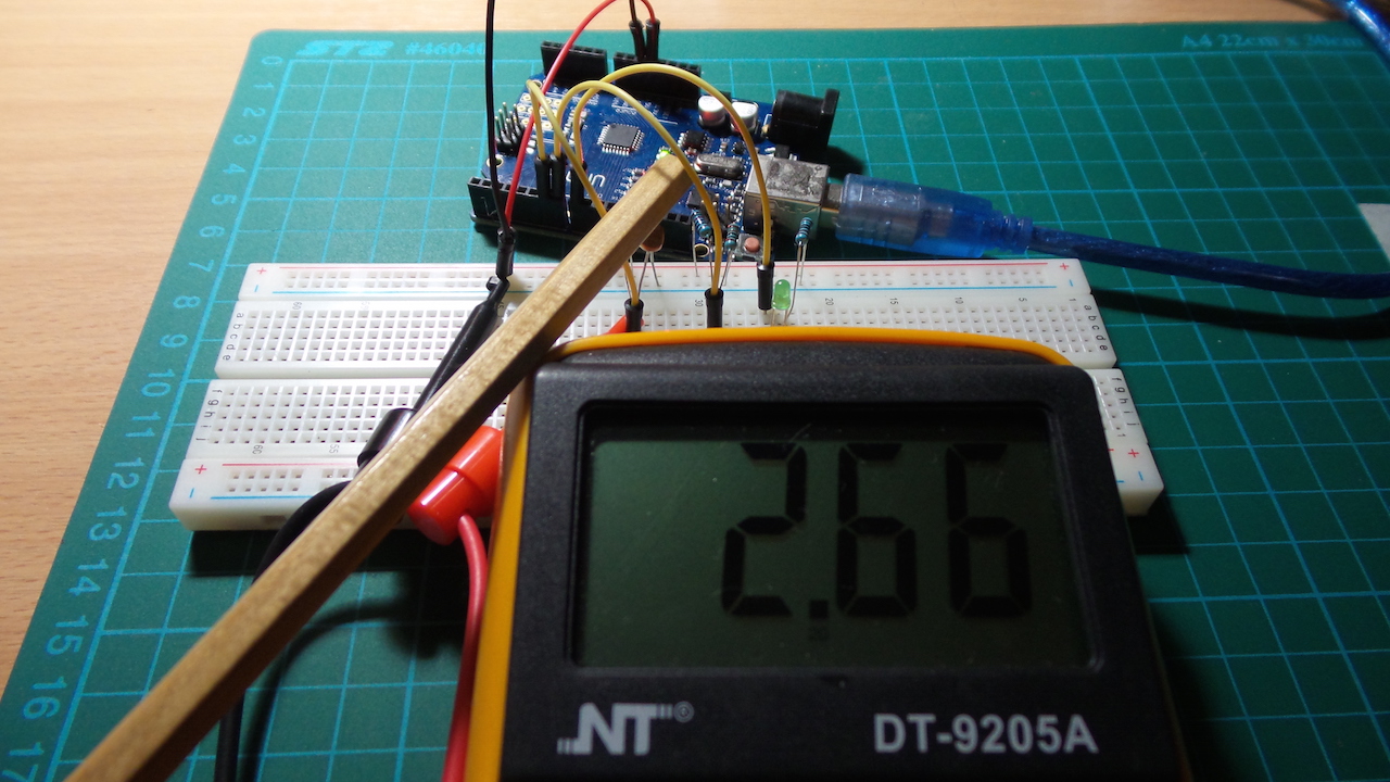
Construction
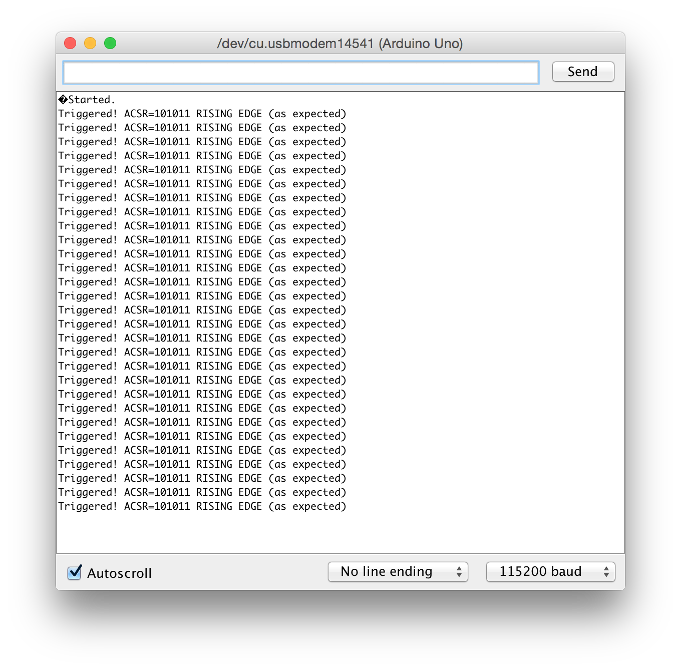
Typical Console Output
Credits and References
- Using the Arduino Analog Comparator - inspired this test!
- AVR128: Setup and Use the Analog Comparator - Atmel application note
- ATmega168 Analog Comparator example
- AVR Libc Reference Manual - Interrupts
- AVR datasheet