
#849 Ultrasonic Levitator Kit
Investigate acoustic levitation by building a cheap ultrasonic levitator kit that uses common 40kHz ultrasonic transmitters driven by STC15F101W microcontroller and a TC4427 power MOSFET.
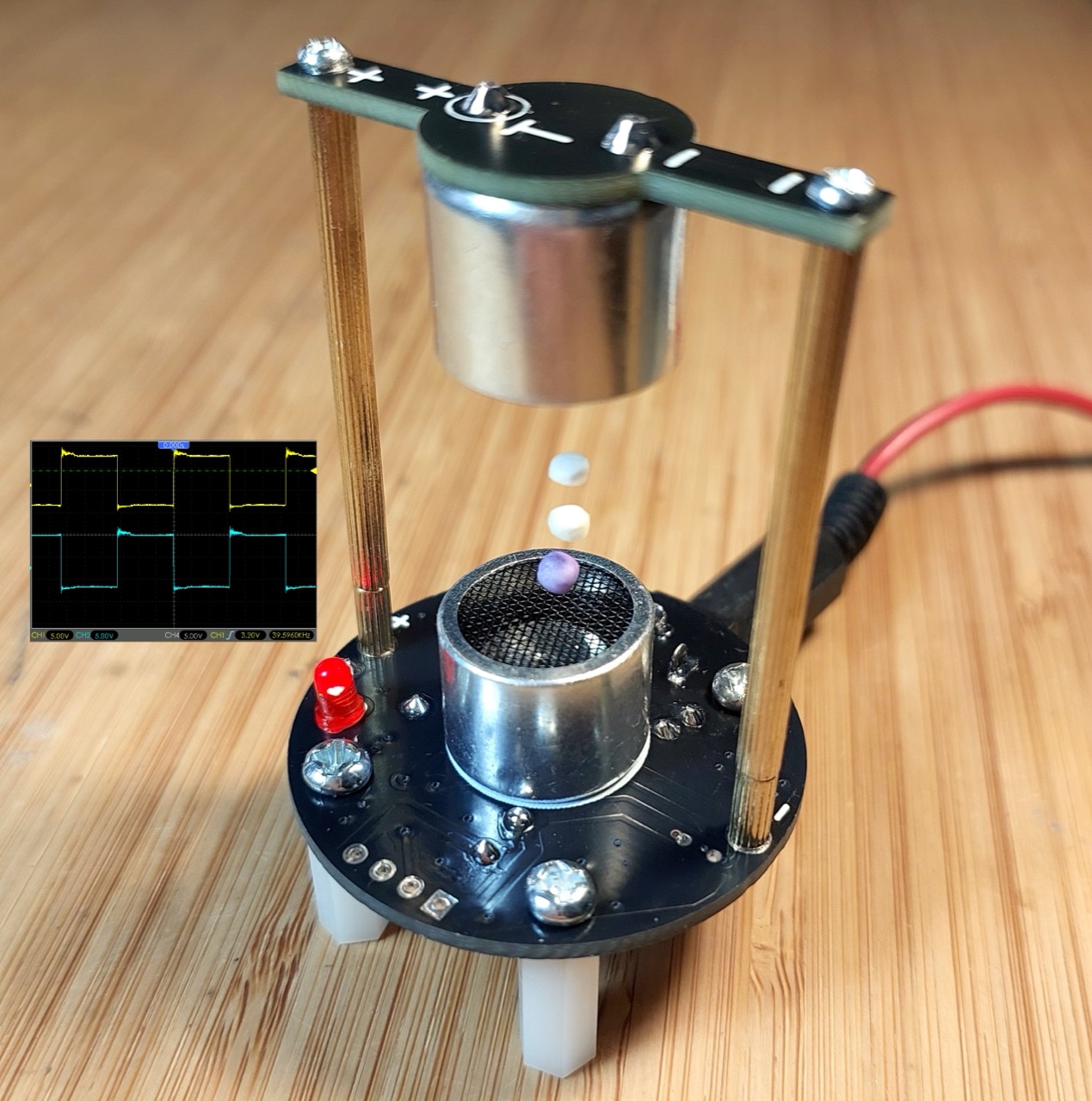
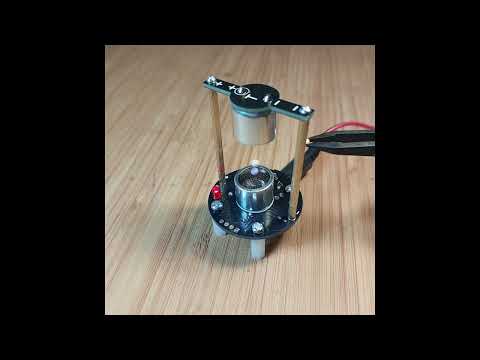
Here’s a quick demo..
Notes
I remember videos of acoustic/ultrasonic levitation going viral some years ago, and always planned to give it a go. When I saw a kit “DIY Kit Ultrasonic Levitator Suspension Standing Wave Controller DIY Learning Kit Scientific Teaching Experiment Soldering” (aliexpress seller) for SG$4.96, I snapped one up (Jun-2026).
The first demonstration of acoustic levitation using cheap ultrasonic transducers was developed by researcher Dr. Asier Marzo and his team at the University of Bristol in 2017. Prior to that, acoustic levitation was heavily restricted to high-end physics laboratories.
The team used 40kHz ultrasonic transducers, as covered in LEAP#856 TCT40-16. They are commonly found in hobbyist microcontroller modules like the HC-SR04, as used for example in LEAP#287 Ultrasonic Alarm.
The team also published data on a simplified “MiniLev” variation. This version uses just two 40T transmitters facing each other vertically at a precise distance (a factor matching the 8.6mm wavelength of a 40 kHz sound wave). This two-transducer setup forms the blueprint for most demonstrations and kits (like the one I have here).
Kit Specification
Features:
- This is a small ultrasonic suspension device, which can suspend foam balls;
- The suspending device operates at a frequency of 40KHZ in the air, and can capture light objects with a density of 2-3MM in diameter, such as foam balls, ants and other small objects that are stably suspended in the air for a long time, and the main board is slightly heated;
- The circuit is mainly composed of a single chip computer, a driver chip and two ultrasonic emitters;
- It is mainly used to learn about ultrasonic standing wave suspension.
- It is suitable for students or DIY electronics enthusiasts to learn ultrasonic suspended standing wave.
Parameters:
- Power input: DC 12V (0.5-1A)
- Frequency: 40KHZ
- Working temperature: -25˚C~85˚C
- External dimension (finished product): length 44 mm x width 40 mm x height 66 mm
Working principle: ultrasonic standing wave levitation is through the existence of a certain distance (called the resonant cavity distance) between the ultrasonic transmitting end and the transmitting end (or another transmitting end). The transmitted wave and the reflected wave (or another acoustic wave) are continuously superimposed to finally form a standing wave. The acoustic force on the object at the standing wave node overcomes the gravity effect and finally achieves the levitation effect.
Parts
| Component name | Ref | Qty |
|---|---|---|
| Upper PCB board | 1 | |
| Lower PCB | 1 | |
| Ultrasonic transmitter 40T | J3,J4 | 2 |
| M2 * 4 screw | 5 | |
| M2 * 7 two-way copper column | 2 | |
| M2 * 39+3 copper column | 2 | |
| M3 * 6 screw | 5 | |
| M3 * 15 two-way nylon column | 4 | |
| 100µF 25V | C3 | 1 |
| DC005 socket | J1 | 1 |
| 104 Monolithic capacitor | C1,C2 | 2 |
| 4.7kΩ resistance | R1 | 1 |
| 3mm LED red | LED1 | 1 |
| 1117-5.0 regulator SOT-223 | U1 | 1 |
| STC15F104W (pre-programmed) | U2 | 1 |
| TC4427 Dual High-Speed Power MOSFET | U3 | 1 |
Circuit Design
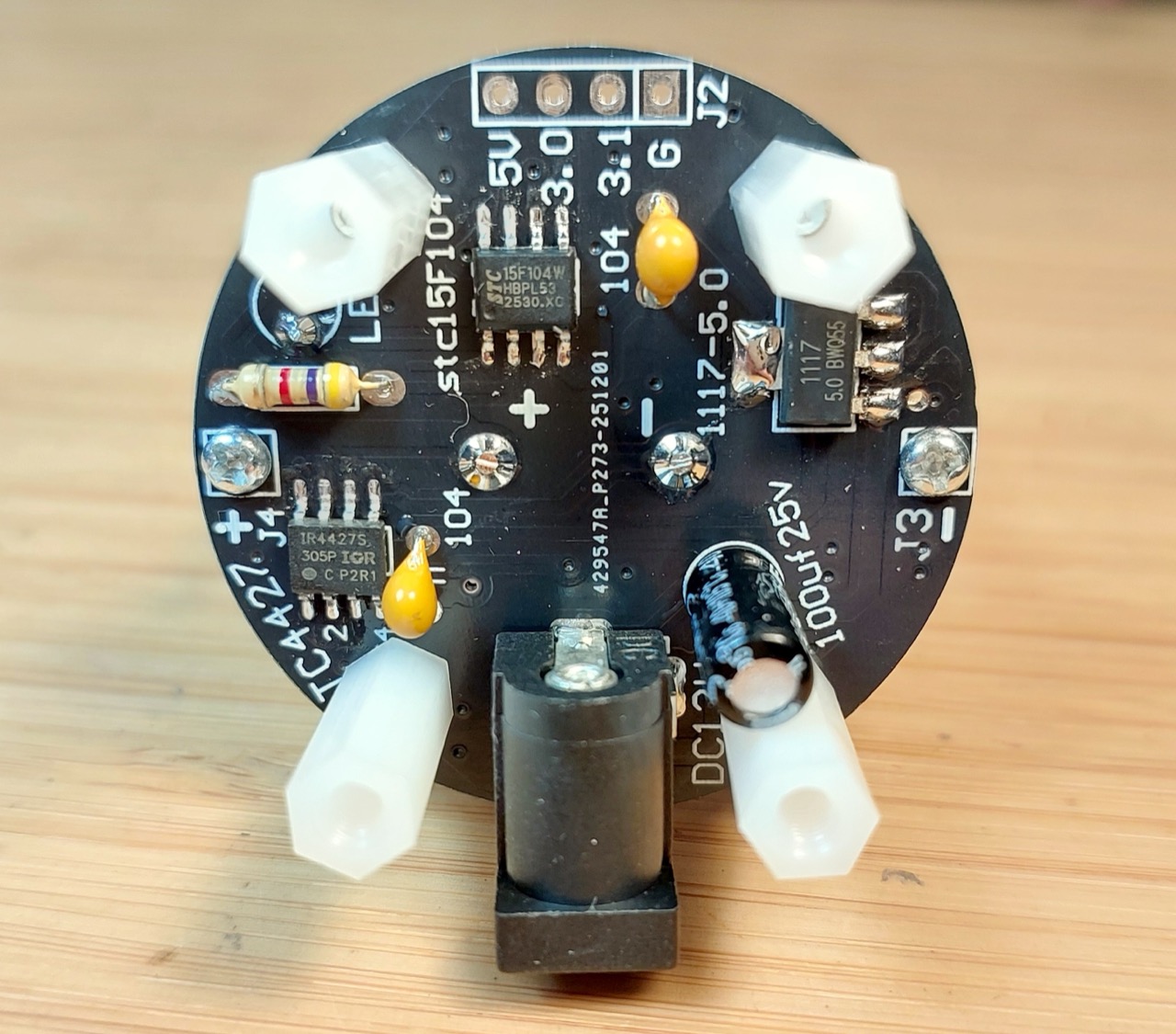
This is a quick redrawing of the circuit with Fritzing: see UltrasonicLevitatorKit.fzz.
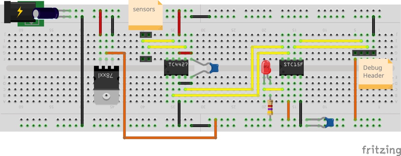
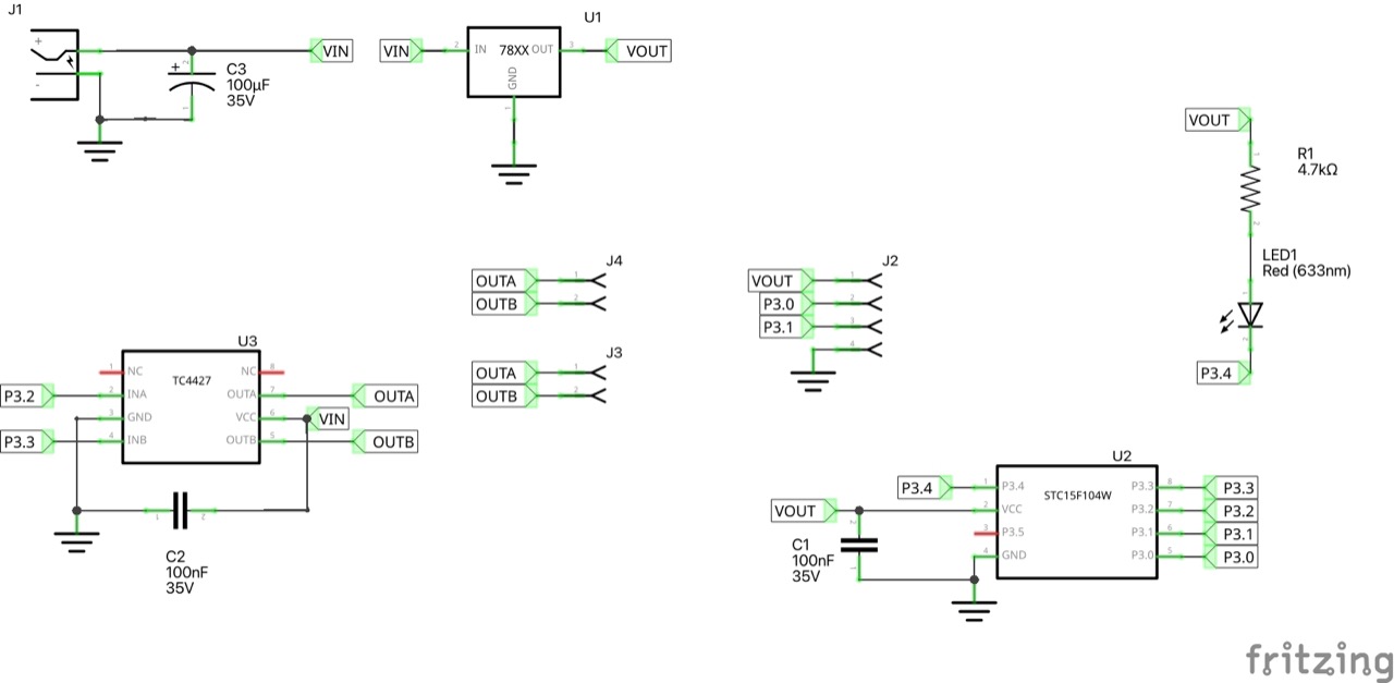
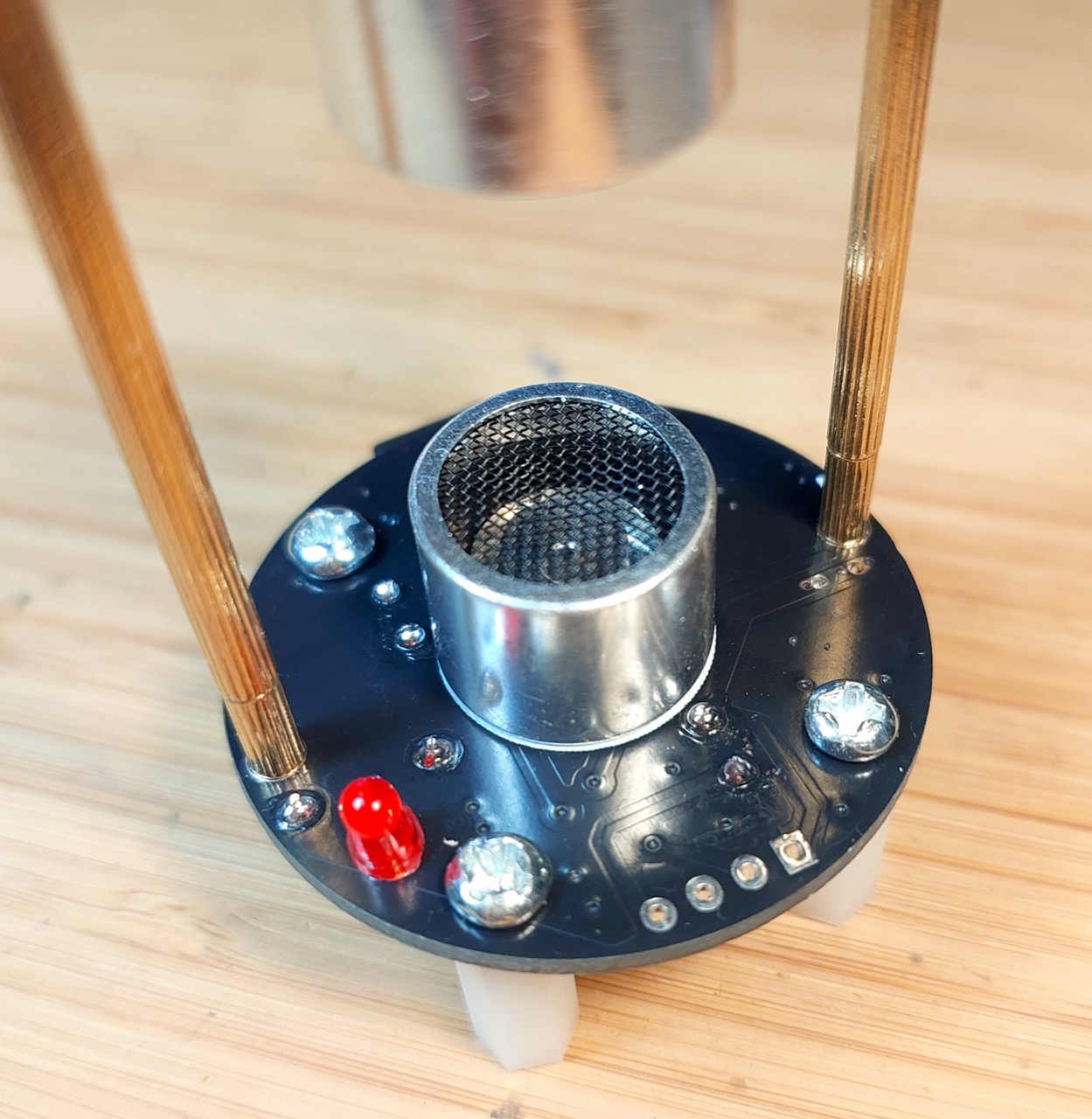
As a soldering kit, it is a nice quick exercise with just a few SMT and through-hole components. goes together without any issue.
Notes:
- that ultrasonic transmitters are polarised. The lead with a distinct insulator is the +ve lead that should correspond to the “+” on the PCB
- PS: since they are single units driven with an AC signal, I suspect the orientation may not actually matter, as long as the same top and bottom
- I chose to insert the LED so that it is visible from the top of the finished board, but it may be installed more discretely on the underside.
Performance
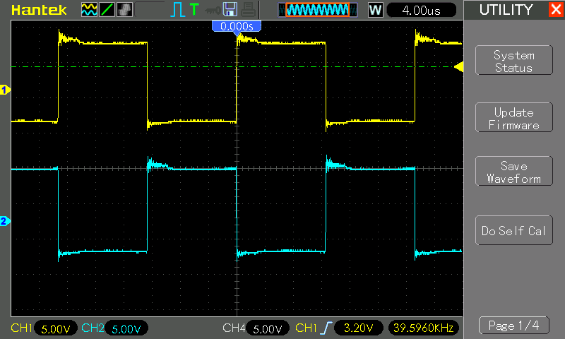
The following scope trace captures the positive (CH1 yellow) and negative (CH2 blue) connections to the ultrasonic sensors.
Basically the microcontroller is simply driving the sensors via the TC4427 Power MOSFET at ~40kHz
Code
Source code was not provided with the kit or by the manufacturer (as far as I can tell). I imagine it is nothing special however, as it just needs to generate square waves at a fixed frequency. Code for similar projects is widely available and open source.
I did attempt to dump the program code, using the STC ISP Programming Software connected to the programming pin holes included on the PCB. I had no success though: STC-ISP was unable to get any response or identify the STC15F104W despite all my jiggly-pokery.
Credits and References
- LEAP#856 TCT40-16.
- LEAP#287 Ultrasonic Alarm
- “DIY Kit Ultrasonic Levitator Suspension Standing Wave Controller DIY Learning Kit Scientific Teaching Experiment Soldering” (aliexpress seller)
- Purchased for SG$4.96 (Jun-2026)
- AMS1117 datasheet
- STC15F101W series
- TC4427 datasheet
- https://en.wikipedia.org/wiki/Acoustic_levitation
- https://makezine.com/projects/micro-ultrasonic-levitator/
- https://www.instructables.com/Acoustic-Levitator/