
#751 Electro-mechanical Clock Mechanism
Examining a common crystal-disciplined quartz clock movement mechanism, figuring out how to tap a 1Hz timing signal.

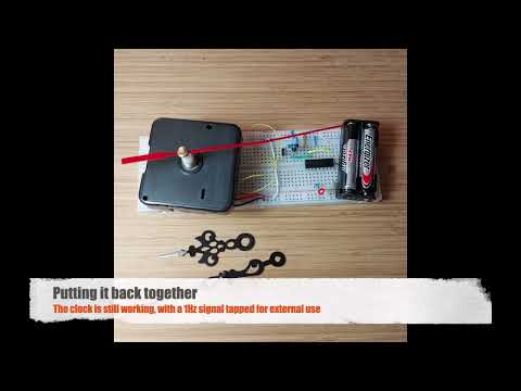
Here’s a quick demo..
Notes
Quartz Clock Movement


The “quartz” mechanism is encased on a potted PCB labelled “SY09”. The hidden circuitry divides the 32768Hz crystal by 4096 to produce an 8Hz pulse. The 8Hz pulse is used to energize the coil and spin the ferrite/magnetised first drive gear.

The SY09 PCB decoded:

Measuring the scaled pulse that drives the coil on an oscilloscope:

Circuit Design
Now that I’ve identified the 8Hz signal produced by the SY09 board, let’s have some fun and reduce it further to 1Hz with a CD4017 decade counter. An LED is attached on “0” output, and “8” wired to reset to convert the CD4017 into a divide-by-8 counter.
Why would I want to do this? Well, it may have something to do with the 2025 Hackaday One Hertz Challenge!


Re-assembly with Power wires (red/black) and 8Hz clock signal (yellow) attached:


Checking the result on an oscilloscope, we get a clean 1 Hz pulse:

See it in action:
Reduction Gear Assembly
This is mainly for my reference so I can re-assemble the gearing correctly!


Credits and References
- DIY Wall Clock Quartz Movement Mechanism Black Red Removable Wall Clock Quartz Hour/Minute Hand Clock Movement - similar clock movement mechanism from an aliexpress seller
- CD4017 datasheet