
#534 ESP-12 Programming
The basics of programming an ESP-12 with the ESP8266 core for Arduino.

Here’s a quick demo..
Notes
I bought some ESP-12E ESP8266 modules a while back, along with some adapter boards but they’ve been sitting in a drawer ever since. Time to crack them open!
NB: I purchased the ESP-12E module for US$1.92 in Mar-2016, currently listing for SG$1.39 in Jan-2026. The adapters were US$1.25 for 10 in Oct-2017, currently listing for SG$1.70 for 10 in Jan-2026.
These notes cover the basics of programming the devices with ESP8266 core for Arduino, using the Arduino IDE.
ESP-12E Features

- 20 active pins
- GPIO 0-15 all have a built-in pull-up resistor, just like in an Arduino.
- GPIO16 has a built-in pull-down resistor.
- GPIO2 has a built-in LED (may be on GPIO1 on other boards)
- 4Mib flash
- Requires 3.3V supply
- PCB trace antenna
For more board specifications and comparisons, see https://en.wikipedia.org/wiki/ESP8266#Ai-Thinker_modules
Construction
I’m using a breadboard layout with:
- the ESP-12 on an adapter board
- separate 3.3V power supply for the ESP
- CH340 USB to TTL adapter
- level-shifter for 5V signals to/from the USB to TTL adapter


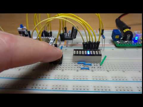
Demo Sketch
The Programming.ino sketch is a simple demonstration of GPIO input and output:
- button press (GPIO13)
- sequences output on GPIO 2, 4, 5, 12, 14, 16.
An LED bar graph module is used for display of the GPIO output.
Installing ESP8266 core for Arduino
See the docs here. Essentially:
- add the Additional Board Manager URL in settings:
https://arduino.esp8266.com/stable/package_esp8266com_index.json - install “esp8266 by ESP8266 Community” in the Board Manager. I have updated to v3.1.2 as of Jan-2026.

Programming with ESP8266 core for Arduino
My selected settings in the Arduino IDE:

The adapter boards have fixed pull-up/down resistors included:
- 10kΩ pull-down on GPIO15
- 10kΩ pull-up on CH_PD
Externally (on the breadboard):
- 10kΩ pull-up on RESET (with pushbutton to pull-down)
- 10kΩ on GPIO0 (switchable as pull-up/pull-down)
Programming mode is engaged by:
- set GPIO0 to pull-down
- toggle reset
Run mode is engaged by:
- set GPIO0 to pull-up
- toggle reset
Compile and push the code with the Arduino IDE:

Credits and References
- ESP-12E: “ESP8266 ESP-01 ESP-01S ESP-07 ESP-12E ESP-12F Remote Serial Port WIFI Wireless Module Intelligent Housing System Adapter 2.4G” (aliexpress seller listing)
- ESP-7/12 adapter boards: “10PC ESP8266 serial WIFI Module Adapter Plate Applies to ESP-07, ESP-12F, ESP-12E for arduino” (aliexpress seller listing)
- ESP8266 Arduino Core - boards doc
- ESP-01/07/12 Series Modules User’s Manual
- Simple Arduino Web Server on ESP-07/ESP-12 Tutorial
- Ai-Thinker ESP8266 modules