
#372 MilliVoltmeter DIY
An ATmega328-based millivolt meter based on a design by Scullcom Hobby Electronics. Uses an LTC2400 ADC and LT1019 voltage reference.
See CustomBoardAndEnclosure for details of the custom PCB and enclosure I made for the project.
Notes
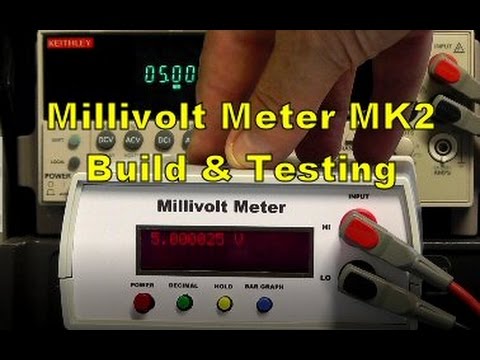
This project is based on the excellent build tutorial by Scullcom Hobby Electronics #44 - Millivolt Meter MK2
A few changes I’ve made:
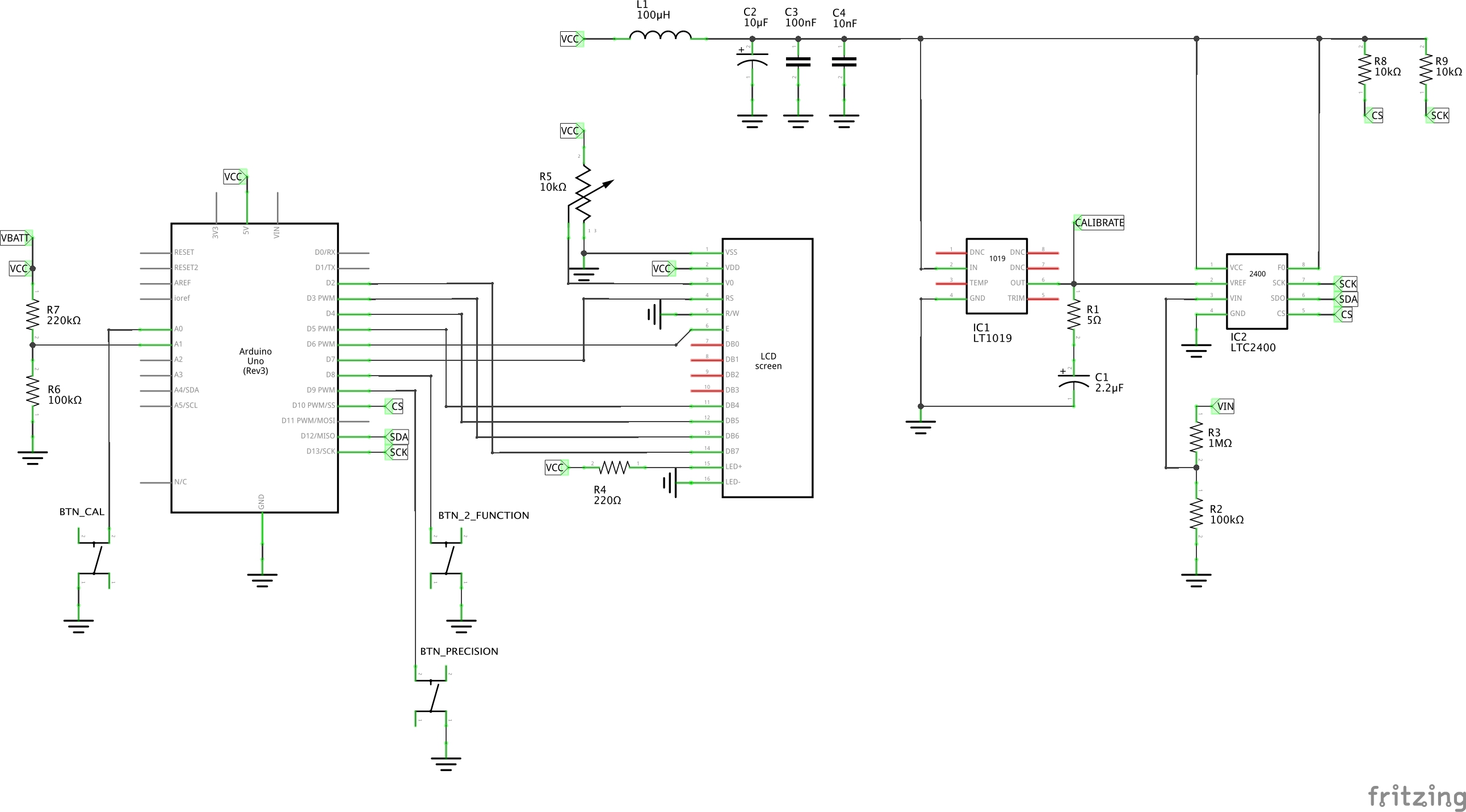
- LT1019 2.5V voltage reference instead of the ADR4540BRZ
- direct LCD control instead of I²C (because it is what I had available)
- some of the buttons moved to analog pins (digital mode) since the LCD uses a few too many pins
- adjust the controls to a three-button command set.
- discarded the op-amp buffer, as I found it skewed the reading at the top and bottom of the range
- altered the calibration method, so the only fixed value in the code is the reference voltage.
Button Functions
I used normally-open push-buttons on the breadboard, but for the final build I have some normally-closed push-buttons.
The #define BUTTON_LOGIC_ACTIVE_STATE is used to select between HIGH or LOW button logic.
Internal pull-ups are enabled so there are no additional external components required other than the push-buttons themselves.
All the necessary functions are implemented with a three-button command set:
- button 1: calibrate
- button 2: change the number of digits (precision)
- button 3: change the second-line function between 3 modes:
- bar graph
- hold value
- raw ADC output
Buffering the Input Voltage
The input signal is tapped from a voltage-divider to provide around 10x attenuation, and therefore support a wider voltage range.
The values used in the voltage-divider are not critical. They just need to be in a suitable proportion to scale back the intended input voltage range to a maximum limit of the reference voltage, and large enough to provide a high-impedance input to the voltage under test.
In my design, I’m using 100kΩ and 1MΩ which support a full-range of around 27.5V
Ideally the reading should be buffered to further reduce coupling with the circuit-under-test, as in the original Scullcom project. I tested buffering with an LMC6482 op-amp, but although it is “rail-to-rail” I found it performed quite poorly at the top and bottom of the range e.g. 0V input still produced a 40mV output on the buffer. I decided to discard the buffer, and just rely on a stiff voltage divider. Note that the Scullcom project used a AD8628ARZ, so perhaps that performs better as a buffer (I will have to get some to try).
I also planned to add a 1N4733 5.1V zener diode to provide some over-voltage input protection (across the lower half of the voltage-divider). However the leakage current introduced a minor non-linearity in the readings. So again, I discarded this idea in favour of the most accurate reading possible.
Using the LTC2400
10kΩ pull-ups are added on the CS and SCK pins to ensure the chip does not go into internal oscillator mode on startup.
The LTC2400 provides a 24-bit measurement with respect to the reference voltage (Vref = x00FFFFFF). This is received in a 32-bit serial stream:
- 4 high bits provide status
- 4 low bits are “sub LSB” and can be discarded without affecting accuracy
- the 24 bits in between are the actual reading
The status bits help decode the reading correctly:
- SIG indicates if reading is positive or negative
- EXR indicates if the reading exceeds the reference range (above or below)
Voltage Reference and Calibration
I’m using an LT1019 2.5V reference (because it is what I had available). This means that the LTC2400 ADC output is all calculated with respect to the 2.5V standard.
I have adapted the code so that the unit performs an automatic calibration with respect to the reference voltage. The only hardcoded value is the reference voltage. How this works:
- the reference voltage is exposed on a “calibration” test point
- the +ve input is connected to the “calibration” test point
- press the “calibration” botton
- the calibration adjustment factor is calculated to ensure an accurate reading of the reference voltage
- the calibration adjustment factor is also stored in EEPROM as the default on startup
As a result - as long as the reference voltage is accurate(!) - this approach is agnostic with regards to any input attenuation set in the input voltage divider.
How Calibration and Voltage Conversion Works
The ADC measures the voltage at the split-point of the voltage divider.
When the 2.5V reference voltage is applied to the +ve input, the ADC reading thus corresponds to “2.5V”.
The code assumes a straight-line relationship with two data points:
- 0V = 0 from the ADC
- 2.5V = the calibrated value from the ADC
Thus given any ADC reading, the voltage = 2.5 * reading / calibration_reading
Test Results
So how well does it perform? Here are some measurements.
- calibration factor: 0x19518F (= 2.5V)
- Note: the DMM used here reads the 2.5V test point as 2.49V
| Power Supply Vin | DMM | mVm | ADC | ADC Check Calc |
|---|---|---|---|---|
| 0.00 | 0.00 | 27mV | 0x4666 | 27mV |
| 0.99 | 1.00 | 1.028V | 0xA69F0 | 1.028 |
| 1.99 | 2.00 | 2.02V | 0x1478CC | 2.02 |
| 2.99 | 3.00 | 3.01V | 0x1E81FC | 3.01 |
| 3.99 | 4.00 | 4.00V | 0x2886B0 | 4.00 |
| 4.99 | 5.00 | 4.99V | 0x329080 | 4.99 |
| 5.99 | 5.99 | 5.98V | 0x3C87A0 | 5.98 |
| 6.98 | 6.98 | 6.95V | 0x466E20 | 6.95 |
| 7.98 | 7.98 | 7.95V | 0x5077C0 | 7.95 |
| 8.99 | 8.98 | 8.94V | 0x5A86C0 | 8.94 |
| 10.00 | 9.98 | 9.93V | 0x6494C0 | 9.93 |
| 11.00 | 10.98 | 10.9V | 0x6E9E30 | 10.92 |
| 11.99 | 11.97 | 11.90V | 0x788BF0 | 11.90 |
Note:
- “Power Supply Vin” is what the power supply said it was delivering
- “DMM” is the reading with a digital multimeter
- “mVm” is the reading with the MilliVoltmeter
- “ADC” is the LTC2400 reading used by the MilliVoltmeter
- “ADC Check Calc” is confirmation of the value reported by the MilliVoltmeter based on the ADC value
So, hmm, there appears to be some skew in the readings obtained from the LTC2400:
- non-zero offset (0x4666)
- skew slightly high below 4V
- skewing slightly low above 4V
While that suggests a need to mathematically fit to a curve with a non-zero offset, that’s not how I expect the LTC2400 to behave.
Am I using the LTC2400 correctly? Re-reading the datasheet I see that while Analog Input Voltage is rated for –0.3V to (VCC + 0.3V), it is qualified by notes, in particular:
Note 14: For reference voltage values VREF > 2.5V the extended input of –0.125 • VREF to 1.125 • VREF is limited by the absolute maximum rating of the Analog Input Voltage pin (Pin 3). For 2.5V < VREF ≤ 0.267V + 0.89 • VCC the input voltage range is – 0.3V to 1.125 • VREF. For 0.267V + 0.89 • VCC < VREF ≤ VCC the input voltage range is – 0.3V to VCC + 0.3V.
Since I have VREF = 2.5V and VCC = 5.0V:
With the 1MΩ : 100kΩ voltage divider on the analog input, the input voltages are actually staying within this band for the tests above: ranging from 0V to 1.091V @ 12V test voltage.
Next step: read the application info in the datasheet more carefully. See LEAP#448 LTC2400 for more on the investigation into getting good results from the LTC2400.
Code
MilliVoltmeterDIY.ino is my version of the code, based on the original Millivolt_Meter_MK2_ver33.ino.
Libraries used:
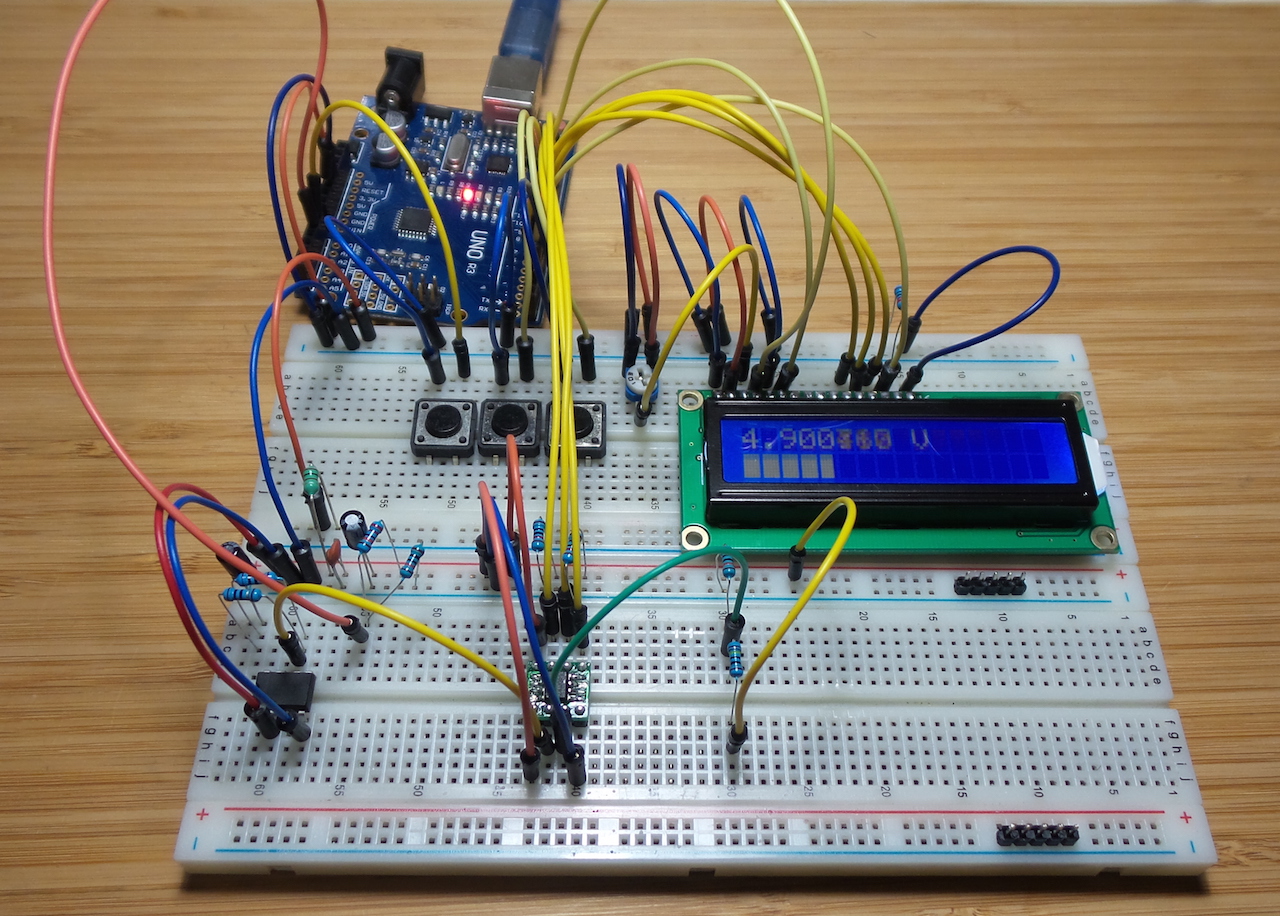
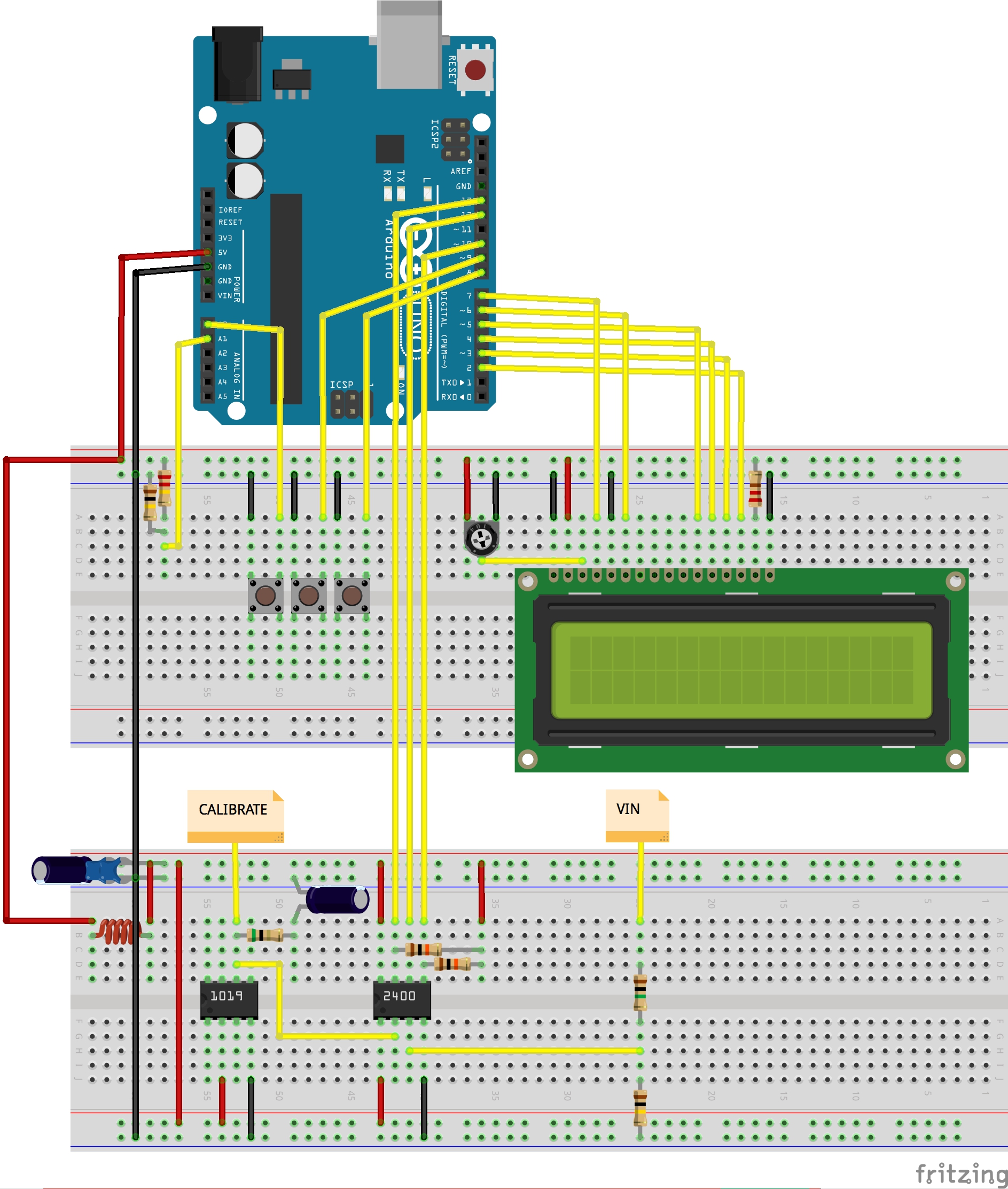
Breadboard Construction
I initially built this on a breadboard and controlled with an Arduino Uno to verify and refine the circuit.
Credits and References
- Scullcom Hobby Electronics #44 - Millivolt Meter MK2 - YouTube
- Millivolt Meter MK2 - more info on on
- Millivolt_Meter_MK2_ver33.ino - original source
- LTC2400 info and datasheet
- LT1019 info and datasheet