#278 Component Tester Kit
Build and evaluate a popular ATMEGA328-based component tester kit
Notes
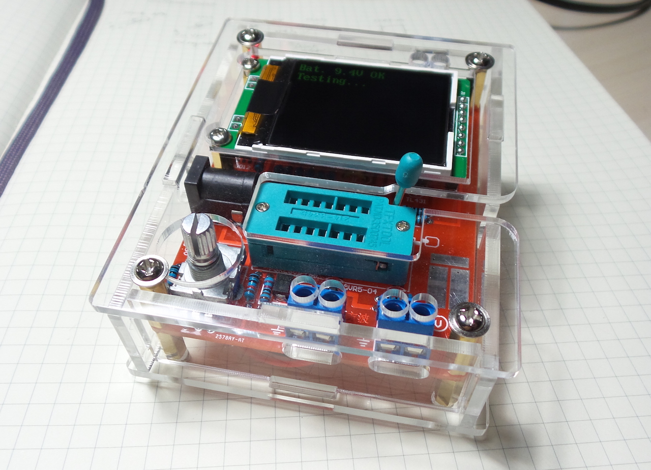
I got a good deal recently on this ATMEGA328-based component tester kit (from seller on aliexpress). The kit is available from a few sources, but not all come with a case. This one came with a purpose-cut clear acrylic case.
It took a few hours to construct, and fired up perfectly. I have built similar circuits myself, but nothing yet with the complete feature list this kit offers.
I believe this kit is another variation of an open source project created by the folks on www.mikrocontroller.net. The Guide to AVR Transistortesters by pfred2 is an excellent introduction.
Parts
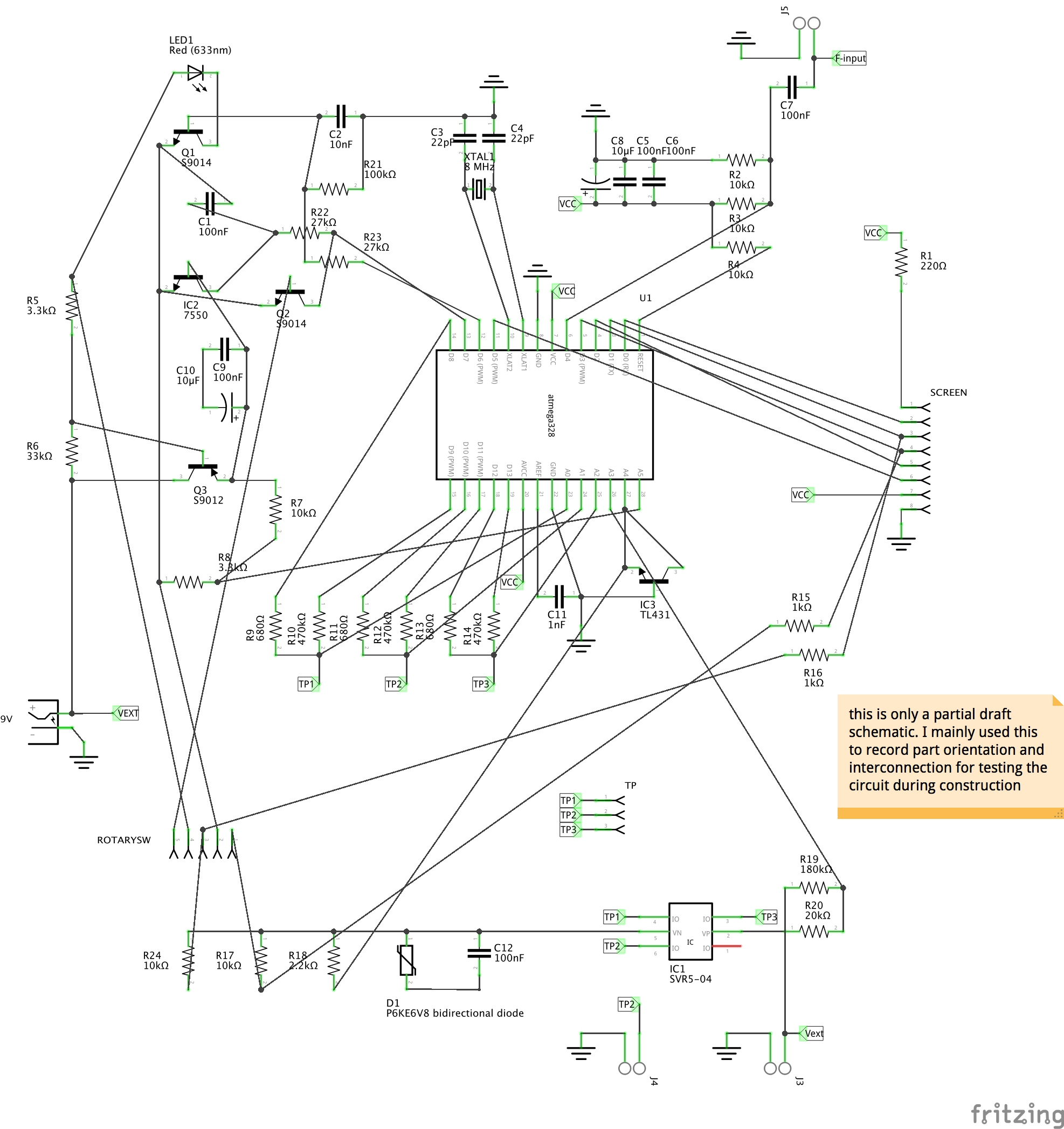
The reference numbers listed below are my own assignation. See the attached schematic.
| Ref | Item | Qty |
|---|---|---|
| R1 | 220Ω | 1 |
| R2,3,4,7,17 | 10kΩ | 6 |
| R5,8 | 3.3kΩ | 2 |
| R6 | 33kΩ | 1 |
| R9,11,13 | 680Ω | 3 |
| R10,12,14 | 470kΩ | 3 |
| R15,16 | 1kΩ | 2 |
| R21 | 100kΩ | 1 |
| R18 | 2.2kΩ | 1 |
| R22,23 | 27kΩ | 2 |
| R19 | 180kΩ | 1 |
| R20 | 20kΩ | 1 |
| C8,10 | 10µF electrolytic | 2 |
| C3,C4 | 22pF ceramic | 2 |
| C11 | 1nF ceramic | 1 |
| C2 | 10nF ceramic | 1 |
| C1,5,6,7,9 | 100nF ceramic | 5 |
| C12 | 100nF smd | 1 |
| Q1,Q2 | S9014 TO-92 | 2 |
| Q3 | S9012 TO-92 | 1 |
| D1 | P6KE6V8C Bidirectional diode | 1 |
| LED1 | 3mm LED red | 1 |
| XTAL1 | 8MHz crystal NSK 9C | 1 |
| IC1 | SVR5-04 V05 Low Capacitance TVS Diode Array - onsemi, farnell | 1 |
| IC2 | HT7550A-1 TO-92 5V regulator | 1 |
| IC3 | TL431A TO-92 precision voltage reference | 1 |
| U1 | Atmel Atmega328P-PU | 1 |
| J1 | barrel jack | 1 |
| LCD | 1 | |
| 9V battery clip | 1 | |
| TFXTOOL 214-3345 | 1 | |
| 2-pin PCB terminal block | 3 | |
| 8-pin PCB header female | 1 | |
| 8-pin PCB header male | 1 | |
| 28-pin DIP socket | 1 | |
| 2578AY-AT switch | 1 |
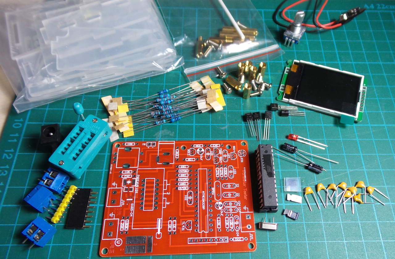
Assembly
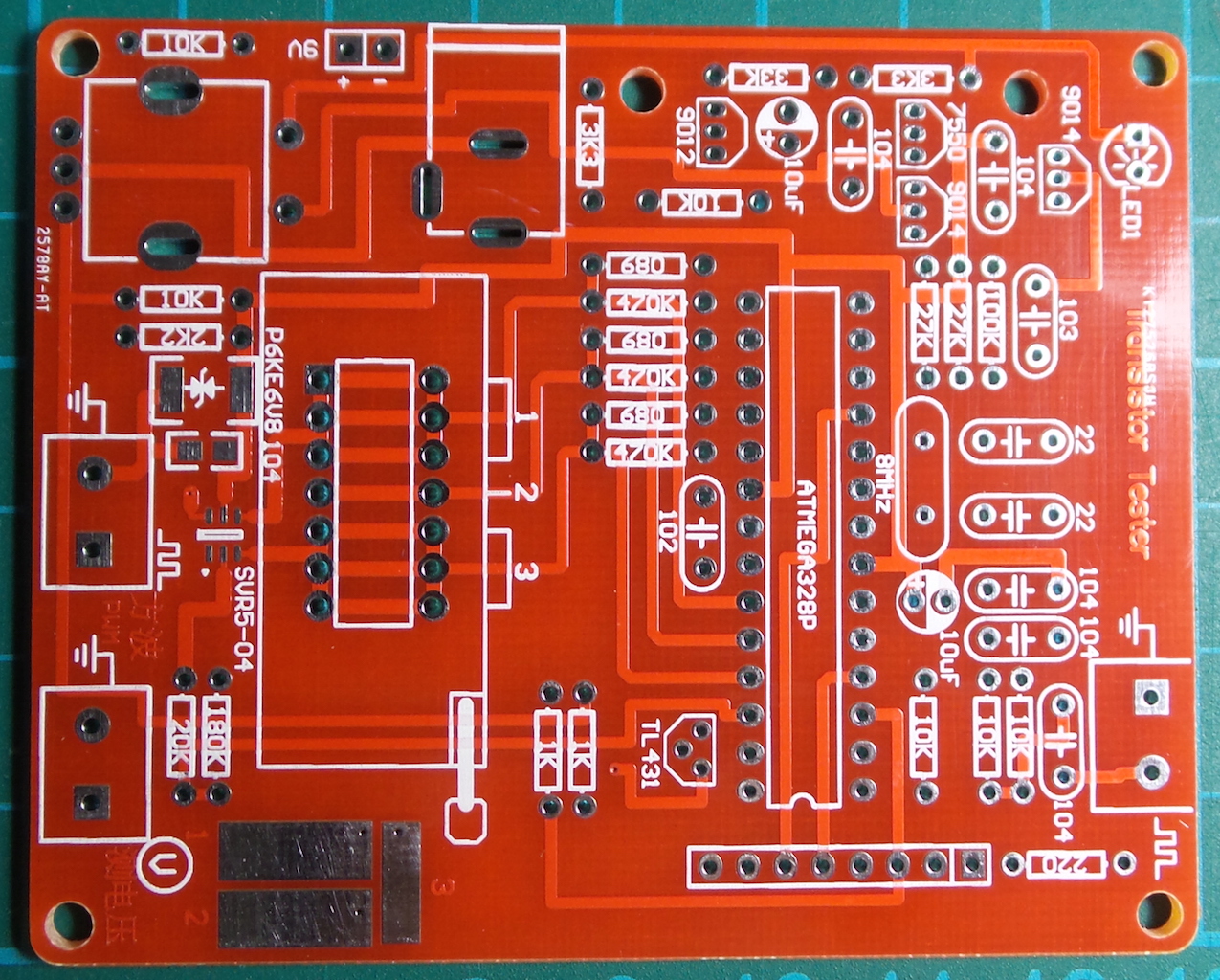
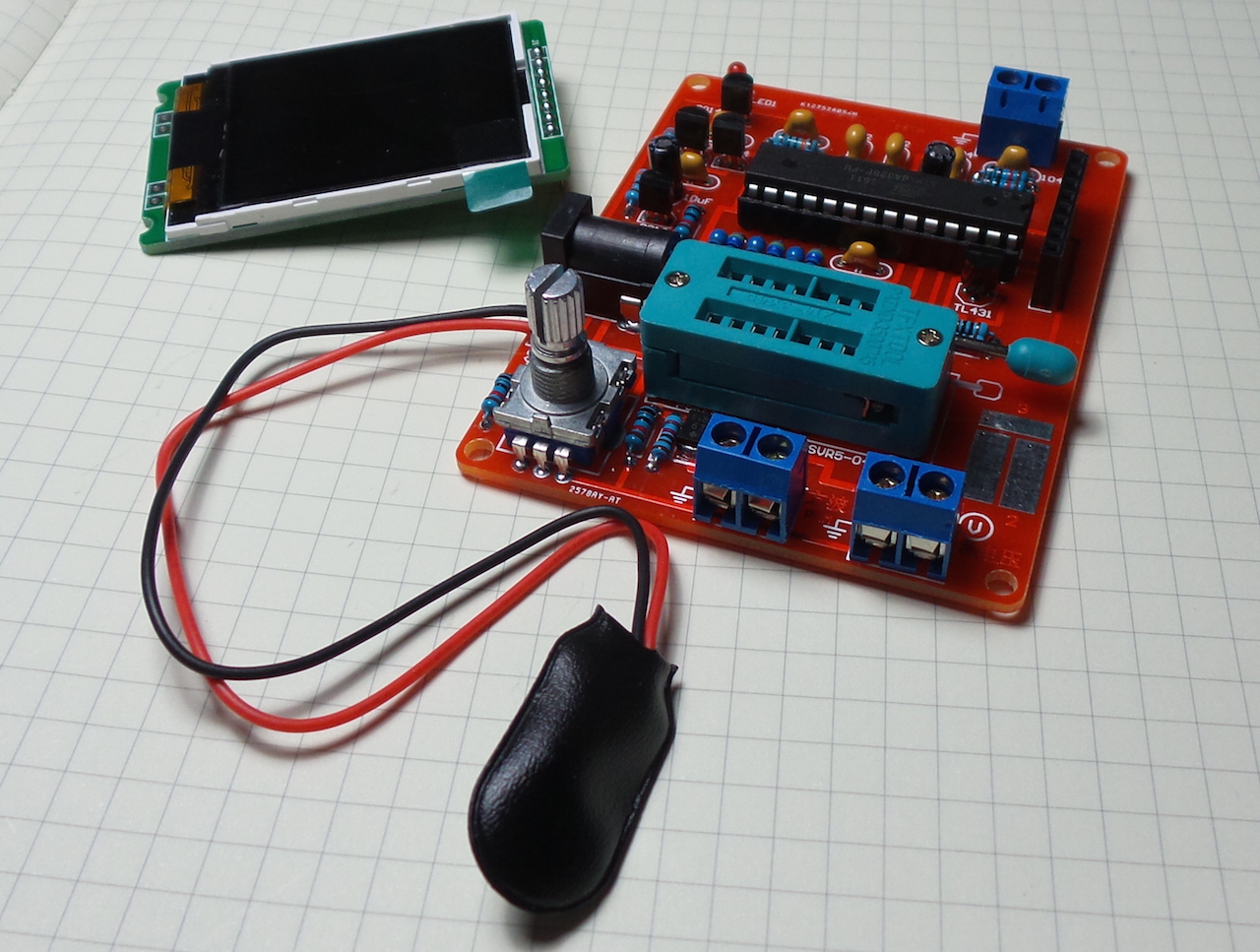
Soldering complete - front view:
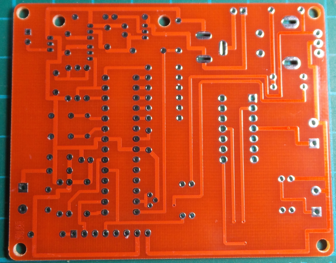
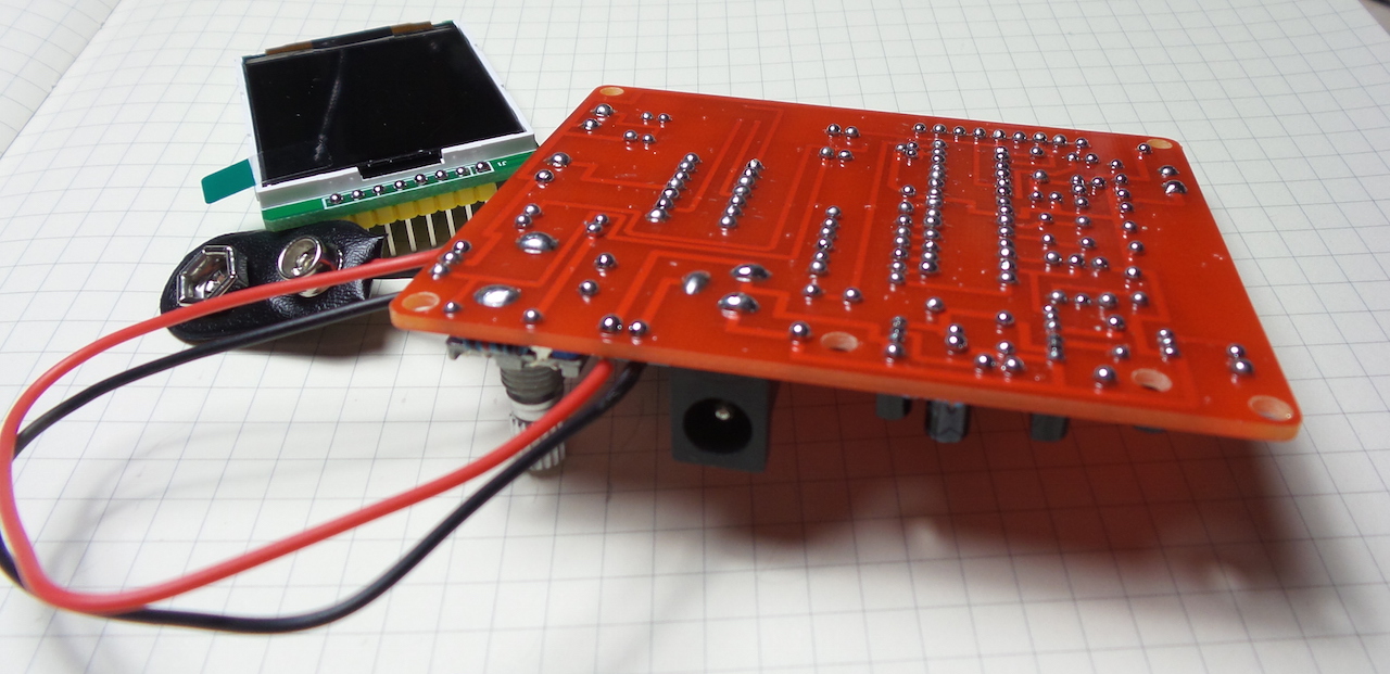
Soldering complete - rear view:
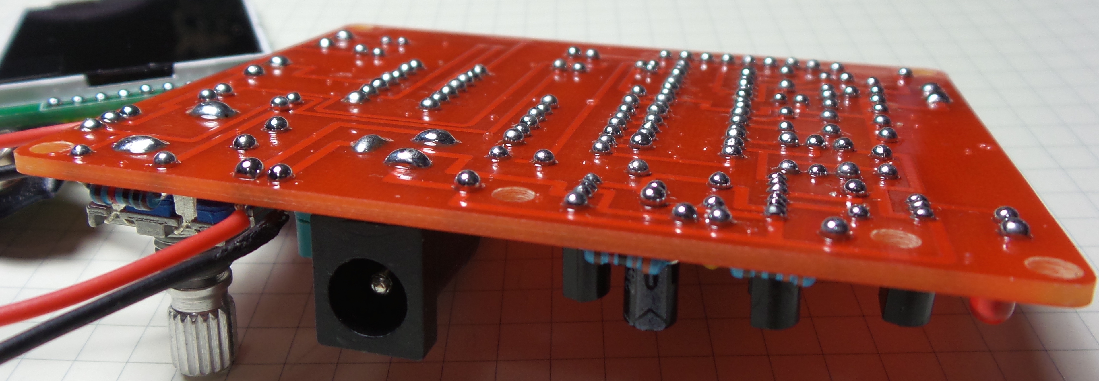
These days every PCB is an opportunity for more BoldportClub-style shiny solder domes:
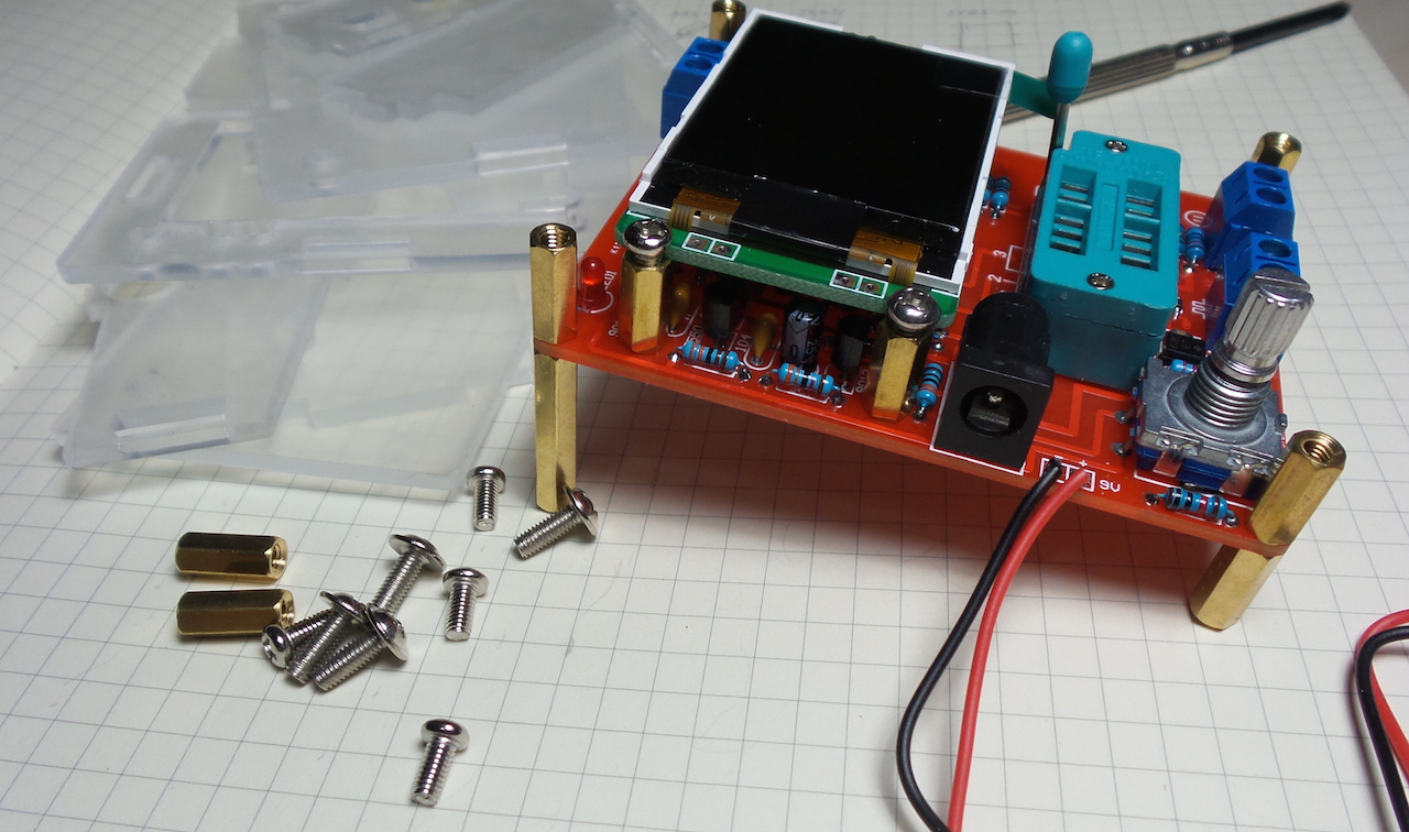
Final case assembly:
Finished product:

Manual & Instructions
The following notes are cribbed from seller product pages..
Power
Transistor Tester can be powered from 6.8V – 12V DC. This can be achieve by a 9V layer-built battery. Two 3.7V Lithium-ion battery in series. Or AC adapter. When power on, the current is about 30mA at DC 9V.
Device will automatically switch off after a test and no further action performed.
Control
Transistor Tester is control by a “rotary pulse encoder with switch” (RPEWS). It supports four operations:
- power on
- short-press
- press and hold (long-press)
- left and right rotation
At the end of a test (before auto-off), a long-press or rotation of the RPEWS will enter the function menu. In the function menu:
- RPEWS rotation changes the selection
- RPEWS short-press selects action
- RPEWS long-press to exit
Self Test and Calibration
Self-test & calibration can be started by either:
- shorting all test points and turning the device on
- selecting it from the function menu
It will prompt with Selftest mode..? .. RPEWS short-press (within 2 seconds) goes into self-test mode.
When test procedure prompts isolate Probes! … remove the shorting of the test points.
The test procedure will then prompt 1-||-3 > 100nf .. insert a 100nF to 20µF capacitor between TP1 and TP3.
Test procedure ends and reports calibration values.
Test Points
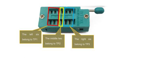
The test socket has three test points (TP1,TP2,TP3). The PCB also has corresponding SMT test pads (unfortunately inaccessible when the tester is mounted in a case)
Function Menu
Brief summary of the function menu options:
- Switch off - what it says! Shut down immediately
- Transistor - component tester (default function at power on)
- Frequency - measure frequency < 25kHz
- f-Generator - signal generator
- 10-bit PWM - 7812.5Hz PWM (Pulse Width Modulation) generator
- C+ESR@TP1:3 - stand-alone capacitor and ESR (Equivalent Series Resistance) measurement
- Selftest
- Voltage - voltmeter < 50V
- Show data - display diagnostics
- FrontColor - change font color
- BackColor - change background color
-
1- -3 - small capacitance measurement - 1- -3 - resistance and inductance measurement
- DS18B20 - 1-wire digital thermometer sensor measurement
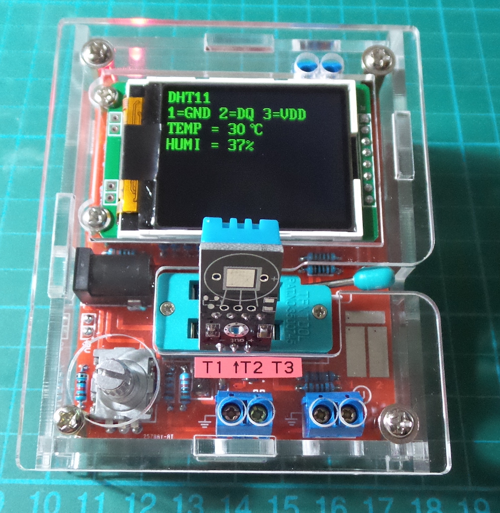
- DHT11 - temperature and humidity sensor measurement
- IR_decoder - IR receiver decoder
- IR_Encoder - simulation of IR Remote Controller
- C(uF)- correction - set the correction value for big capacitor measurement
Component Tests and Features
Usage Hints
Normally the Tester shows the battery voltage with every start. If the voltage fall below a limit, a warning is shown behind the battery voltage.
If you use a rechargeable 9V battery, you should replace the battery as soon as possible or you should recharge.
The measured supply voltage will be shown in display row two for 1 second with VCC=x.xxV.
Capacitors should be discharged before measuring. Otherwise the Tester can be damaged before the start button is pressed.
If you try to measure components in assembled condition, the equipment should be all ways disconnected from power source.
Furthermore you should be sure, that no residual voltage reside in the equipment.
If you try to measure little resistor values, you should keep the resistance of plug connectors and cables in mind. The quality and condition of plug connectors are important, also the resistance of cables used for measurement. The same is in force for the ESR measurement of capacitors. With poor connection cable a ESR value of 0.02ohm can grow to 0.61ohm. You should not expect very good accuracy of measurement results, especially the ESR measurement and the results of inductance measurement are not very exact
Components with problems
You should keep in mind by interpreting the measurement results, that the circuit of the Transistor Tester is designed for small signal semiconductors. In normal measurement condition the measurement current can only reach about 6 mA.
Power semiconductors often make trouble by reason of residual current with the identification and the measurement of junction capacity value. The Tester often cannot deliver enough ignition current or holding current for power Thyristors or Triacs. So a Thyristor can be detected as NPN transistor or diode. Also it is possible, that a Thyristor or Triac is detected as unknown.
Another problem is the identification of semiconductors with integrated resistors. So the base-emitter diode of a BU508D transistor cannot be detected by reason of the parallel connected internal 42ohm resistor. Therefore the transistor function cannot be tested also. Problem with detection is also given with power Darlington transistors. We can find often internal base - emitter resistors, which make it difficult to identify the component with the undersized measurement current.
Two-lead Passives: resistors, capacitors, inductors
These can all be measured in the default test mode between TP1 and TP3.
Two-leaded passive components (resistor, capacitor, inductor) can be tested between any two test points.
If TP1 and TP3 are selected, the test will enter series test mode when the test is complete, else the test may be started again with a RPEWS short-press.
In the component is polarized (for example electrolytic capacitors), favour TP1 for the negative lead/cathode.
Resistors
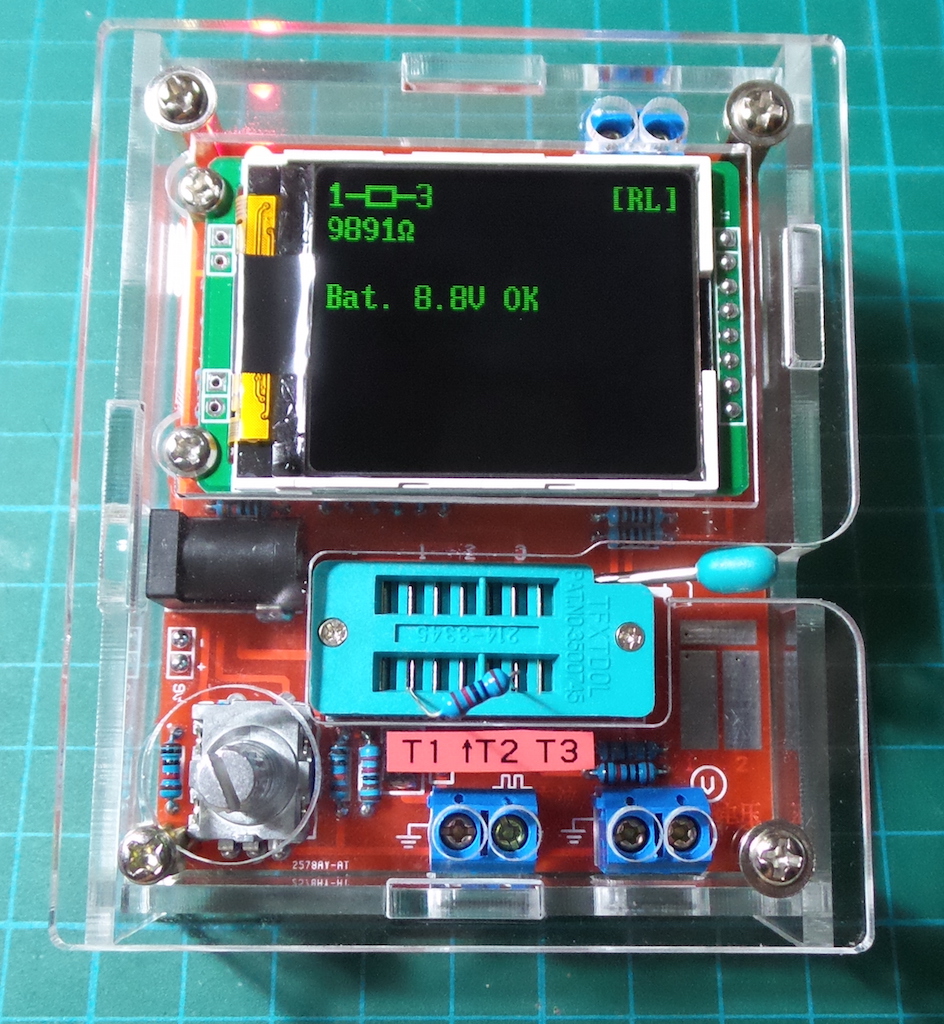
Here’s a 10kΩ resistor under test:
Capacitors
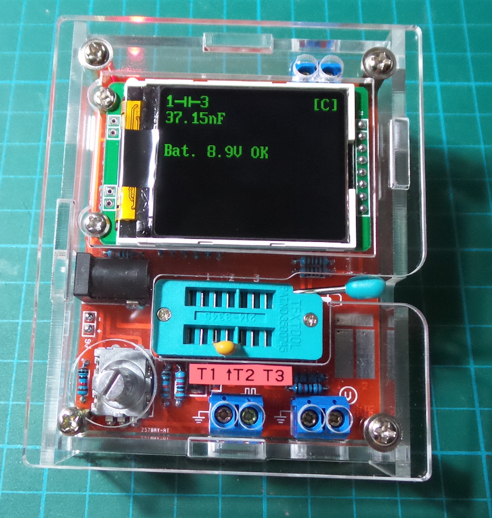
Here’s a 33nF capacitor under test, measured as 37nF:
Attention: All ways be sure to discharge capacitors before connecting them to the Tester. The Tester may be damaged before you have switched it on. There is only a little protection at the MCU’s ports.
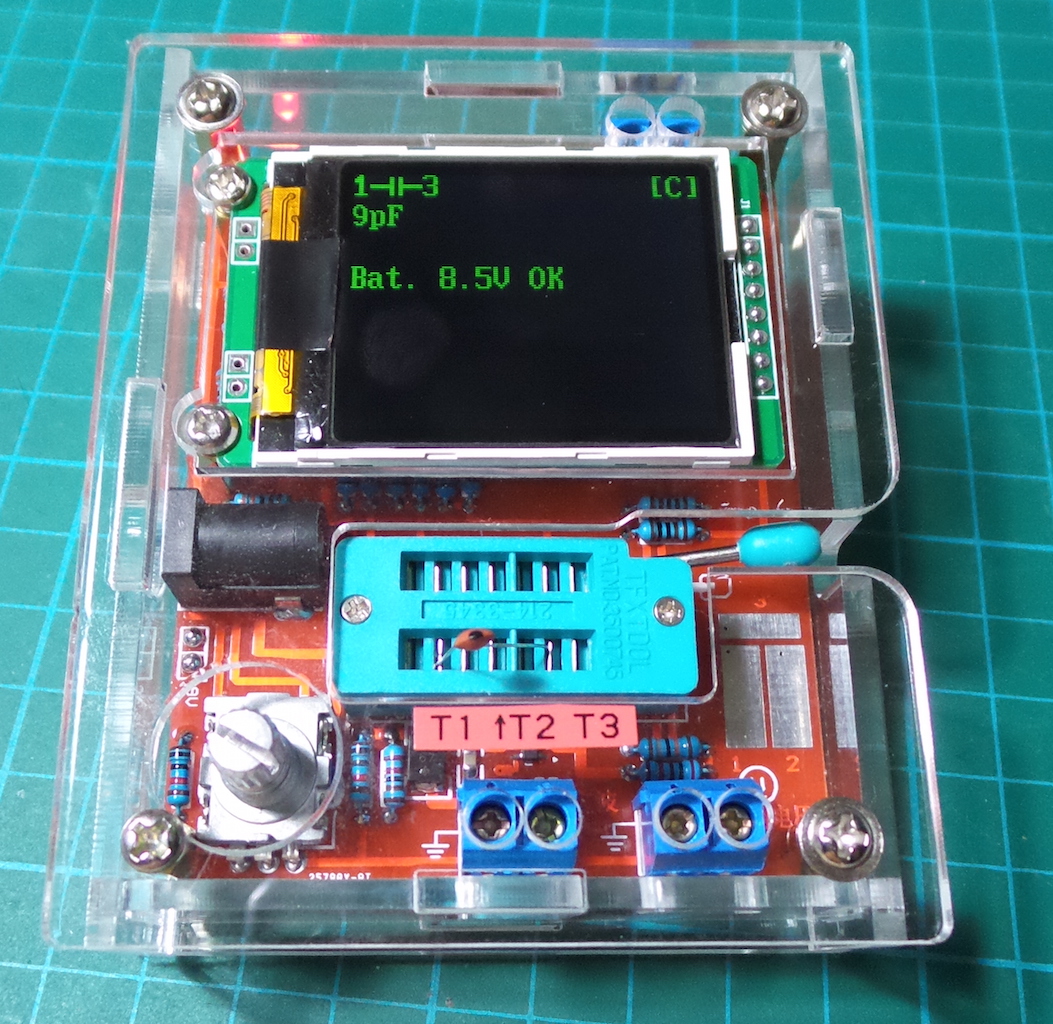
| The “1- | -3” function can measure smaller capacitances than the general tester. Here it is testing a 10pF ceramic: |
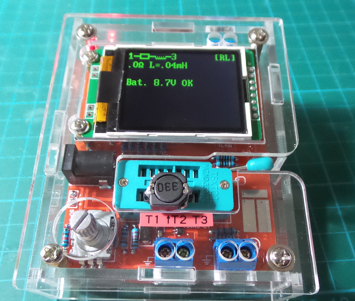
Inductors
Measurement resolution is only 10µH, so it is not possible to measure very small inductors.
Here’s a 33µH, measured as 0.04mH:
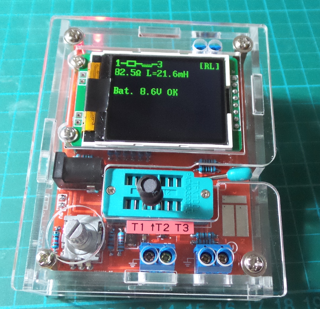
And a 20mH power inductor:
BJT
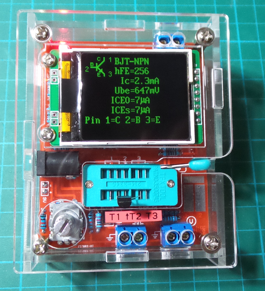
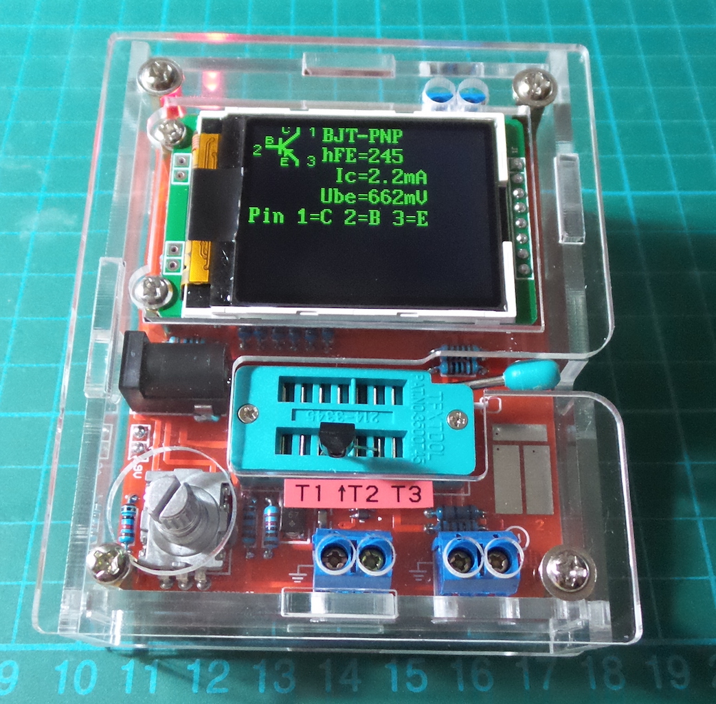
Bipolar junction transistors can be measure with the pins connected in any sequence to TP1, TP2 and TP3. The test will diagnose the type and pin configuration.
Here is a 2N3904 NPN under test:
Here is a 2N3906 PNP under test:
Notes on measuring PNP and NPN transistors
For normal measurement the three pins of the transistor will be connect in any order to the measurement inputs of the Transistor Tester. After pushing the RPEWS, the Tester shows in row1 the type (NPN or PNP), a possible integrated protecting diode of the Collector - Emitter path and the sequence of pins. The diode symbol is shown with correct polarity. Row 2 shows the current amplification factor (hfe=…) and the Base - Emitter threshold voltage. You should know, that the Tester can measure the amplification factor with two different circuits, the common Emitter and the common Collector circuit (Emitter follower). Only the higher result is shown on the LCD.
With Germanium transistors often a Collector cutoff current ICEO with current less base or a Collector residual current ICES with base hold to the emitter level is measured
MOSFET
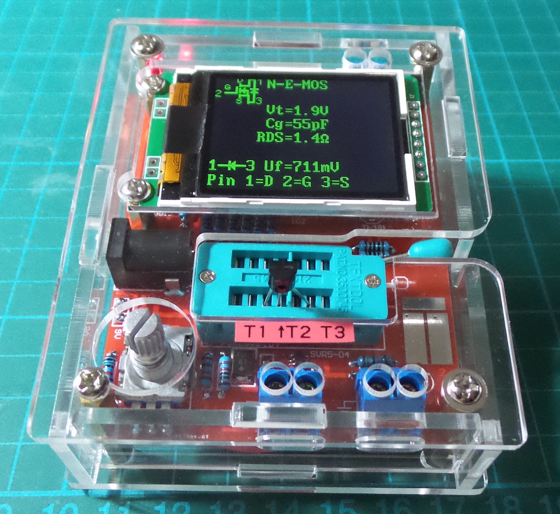
test_nefet
Here is a 2N7000 n-channel MOSFET under test:
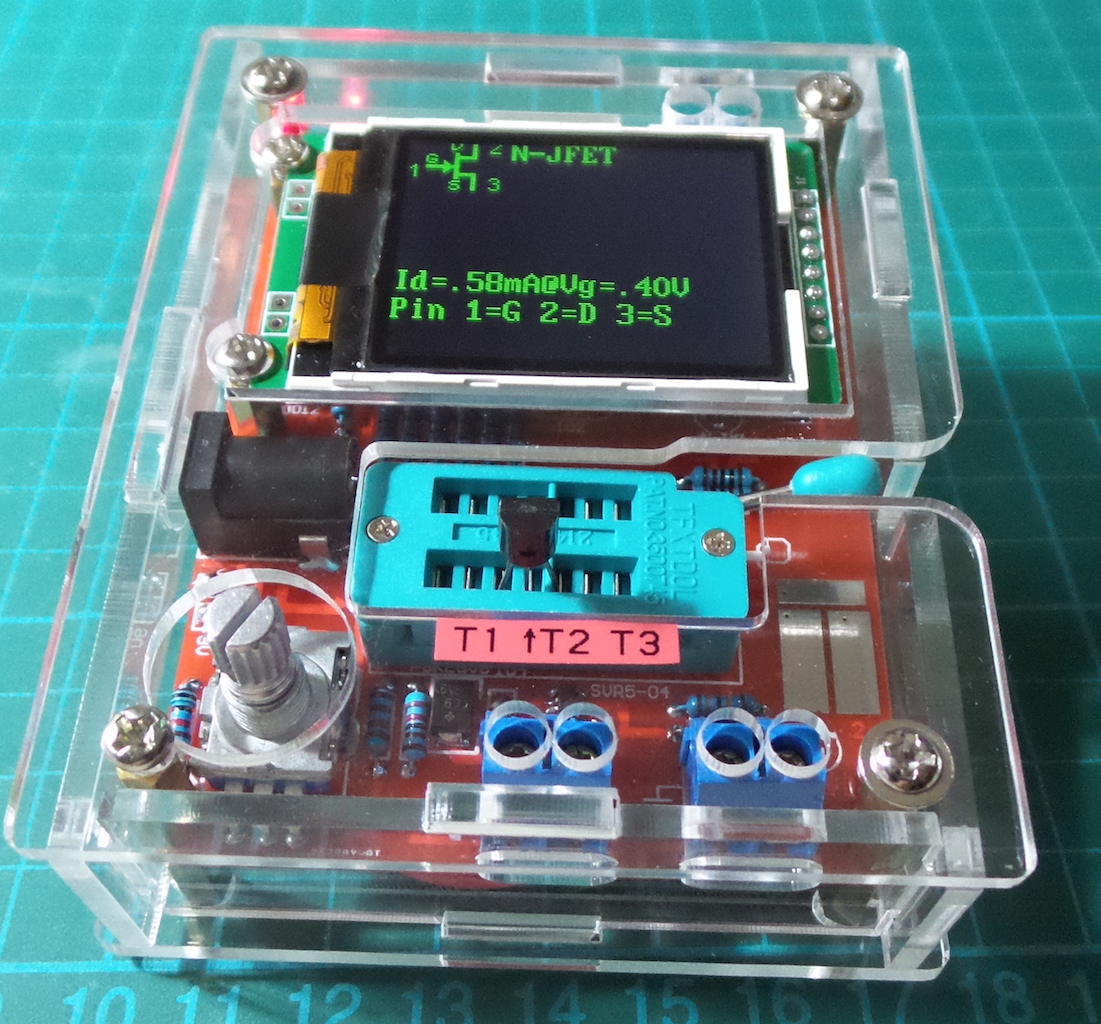
JFET
Here is a J201 n-JFET under test:
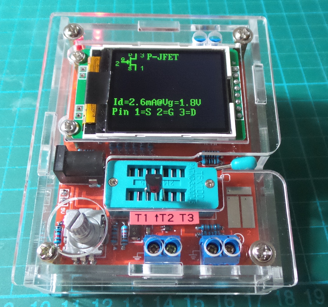
Here is a J175 p-JFET under test:
Notes on measuring JFET and D-MOS transistors
Because the structure of JFET type is symmetrical, the Source and Drain of this transistor cannot be differed. Normally one of the parameter of this transistor is the current of the transistor with the Gate at the same level as Source. This current is often higher than the current, which can be reached with the measurement circuit of the Transistor Tester with the 680Ω resistor. For this reason the 680Ω resistor is connected to the Source. Thus the Gate get with the growing of current a negative bias voltage. The Tester reports the Source current of this circuit and additionally the bias voltage of the Gate. So various models can be differed. The D-MOS transistors (depletion type) are measured with the same method. You should know for enhancement MOS transistors (P-E-MOS or N-E-MOS), that the measurement of the gate threshold voltage (Vth) is more difficult with little gate capacity values. You can get a better voltage value, if you connect a capacitor with a value of some nF parallel to the gate/source. The gate threshold voltage will be find out with a drain current of about 3.5mA for a P-E-MOS and about 4mA for a N-E-MOS
Frequency Measurement (Function “Frequency”)
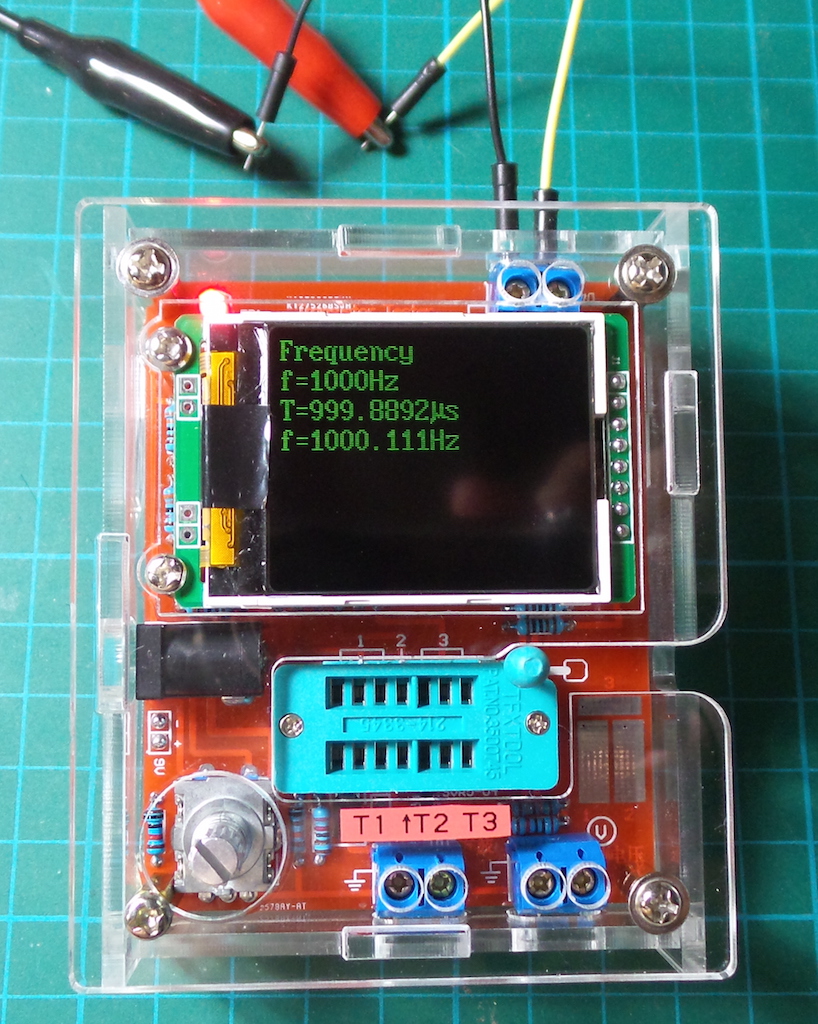
This function measures frequencies up to 25kHz on the upper terminal block (J5). It samples and reports the frequency every few seconds.
Here’s is a 1kHz sine wave, 4V peak-to-peak being measured:
Signal Generator (Function “f-Generator”)
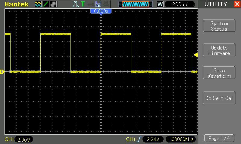
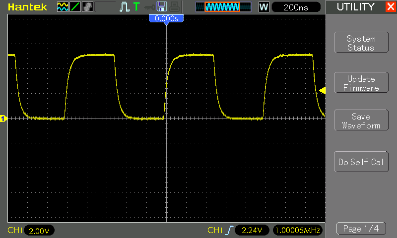
This function produces a square wave on TP2 (also available on the middle-lower connector J4). Frequency is selected from a menu of options rather than being continuously variable.
Some examples captured on an oscilloscope. First, a nice 1kHz wave:
At 1MHz, there is some distortion but still good separation in the signal:
10-bit PWM
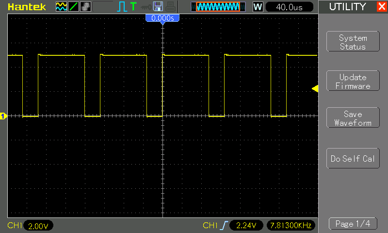
The function ”10-bit PWM” (Pulse Width Modulation) generates a fixed frequency (7812.5Hz) with selectable pulse width at the pin TP2 (also available on the middle-lower connector J4).
Duty cycle is adjustable with a 1% resolution.
- RPEWS short-press increases duty cycle by 1%
- longer RPEWS press increases duty cycle by 10%
- 100% wraps around to 0%
- RPEWS long-press exits the function
PWM wave generated at 75% duty cycle:
Capacitor and ESR Measurement (Function “C+ESR@TP1:3”)
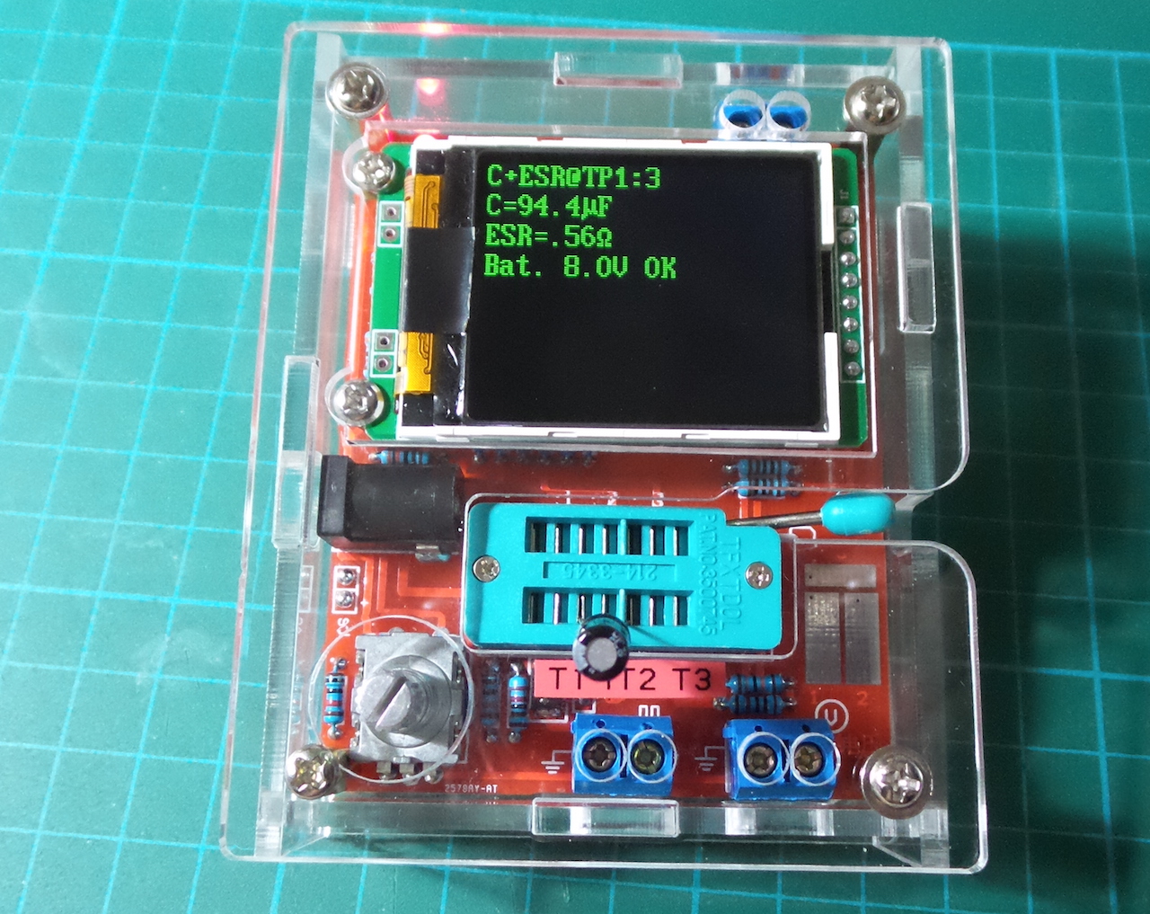
This function is a stand-alone capacitor and ESR (Equivalent Series Resistance) measurement at the test pins TP1 and TP3. Capacitors from 2µF up to 50mF can be measured. Because the measurement voltage is only about 300mV , in most cases the capacitor can be measured ”in circuit” without previous disassembling. The series of measurements can be finished with a long press of RPEWS.
Here’s an example measurement of a 100µF electrolytic (negative connected to TP1):
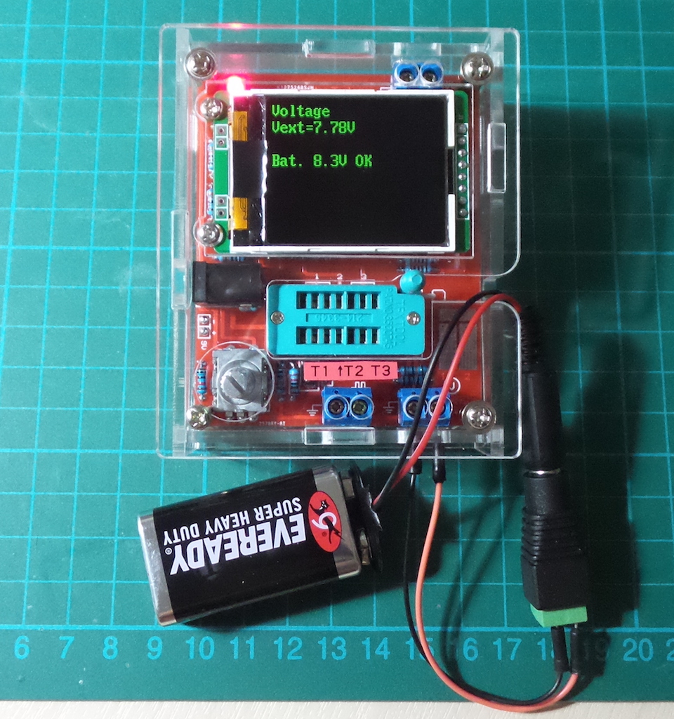
Voltage Measurement (Function “Voltage”)
Voltage measurement is made on the lower right terminal block (J3 - Vext). The measurement can be exited by continuous rotation of the RPEWS.
The maximum external voltage supported is 50V. It is scaled to 0-5V with a 10:1 (180K:20K) voltage divider comprising R19 and R20.
Here’s a measurement of a reasonable flat 9V cell:
Show data
The function ,”Show Data” shows besides the version number of the software the data of the calibration. These are the zero resistance (R0) of the pin combination 1:3, 2:3 and 1:2 .In addition the resistance of the port outputs to the 5V side (RiHi) and to the 0V side (RiLo) are shown. The zero capacity values (C0) are also shown with all pin combinations (1:3, 2:3,1:2 and 3:1, 3:2 2:1). At last the correction values for the comparator (REF C) and for the reference voltage (REF R) are also shown. Every page is shown for 15 seconds, but you can select the next page by a key press or a right turn of the rotary encoder. With a left turn of the rotary encoder you can repeat the output of the last page or return to the previous page.
FrontColor
This function can change the color of the font, the 16bit color is encode in RGB(565) format, that mean red maximum = 31, green maximum = 63,blue maximum = 31 respectively. In the function, a short time press can index the base color to change, turn left decrease it value and turn right increase it value. A long time press will save the Result and exit the function, please keep in mind the FrontColor and the back color cannot be the same. This will case the LCD show nothing. If this happens, you need to do a Selftest , how to enter the Selftest is descriptions at Page 2. Selftest will change the back Color to black and font color to white automatically. When the Selftest is finish . you will have the chance to modify the color .
BackColor
This is function is the same as the FrontColor except it’s change the background color .
Small Capacitance Measurement (Function: “1-||-3”)
The “1-||-3” function can measure smaller capacitances than the general tester between TP1 and TP3. A long-press will exit the function.
Here it is testing a 10pF ceramic:

Series resistance-inductance measurement (Function: “1- -3”)
This function can measurement series resistance and inductance between TP1 and TP3. A long-press will exit the function.
DS18B20
The DS18B20 is a Digital Thermometer with 1 Wire communicating protocol , it Looks like a Transistor due to the component package of TO-92, so it can fit into the Transistor tester.
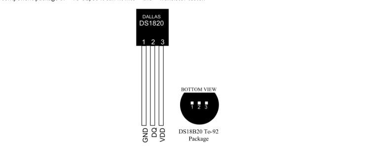
When the function is entered, row 2 of the LCD displays “1=GND 2=DQ 3=VDD”, which indicates device should be connected as follows:
| Pin | Test Connection |
|---|---|
| GND | TP1 |
| DQ | TP2 |
| VDD | TP3 |
Here is a DS18B20 under test:
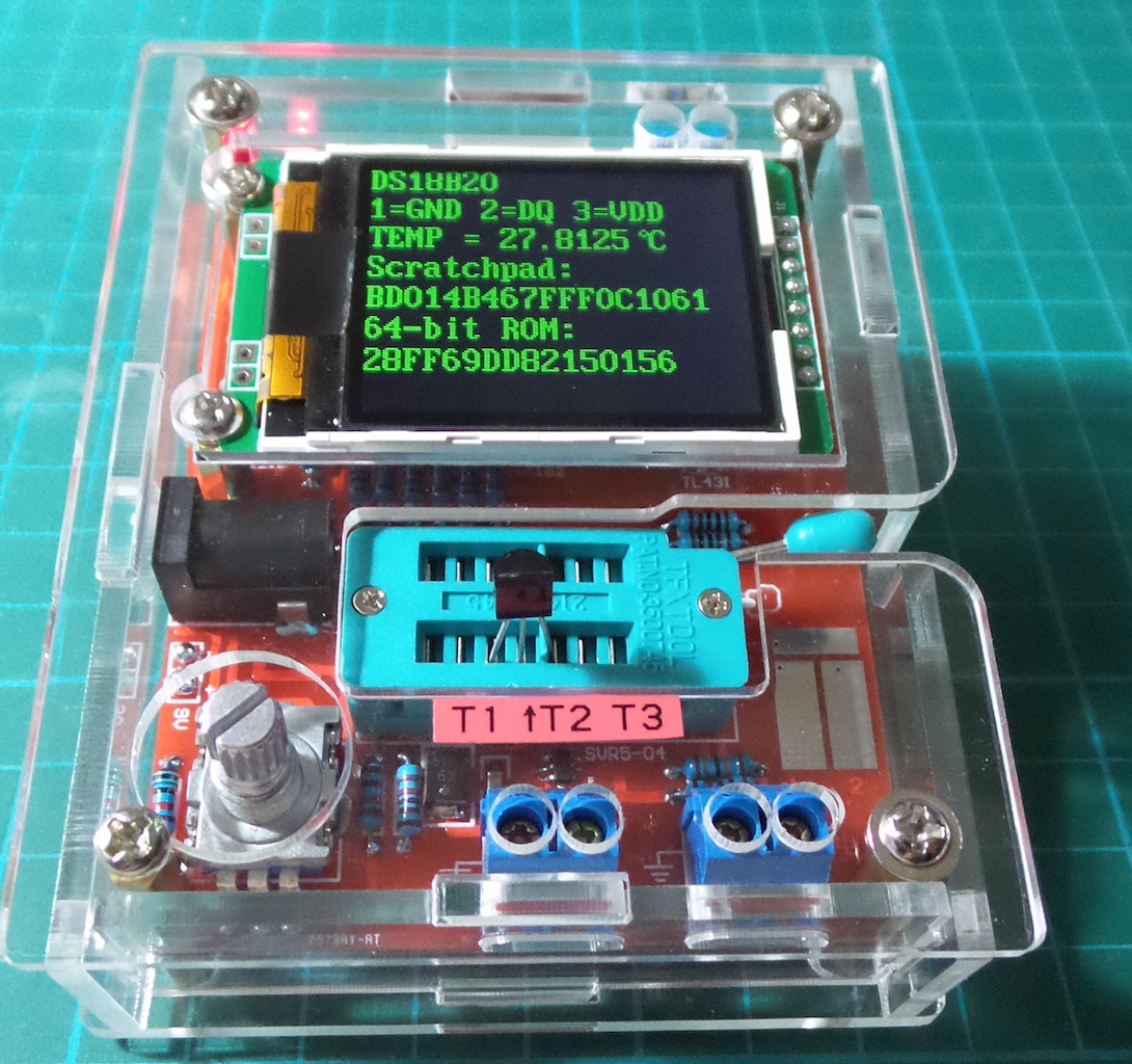
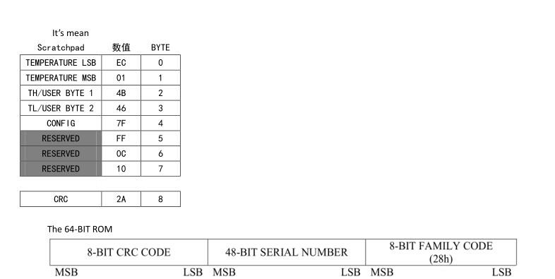
The tester reads the temperature using 12bit resolution. It first starts a “Convert T” [44h] command, and then series reads the 9 bytes of the “SCRATHPAD” and the “64-BIT LASERED ROM”. The first two bytes within the “SCRATCHPAD” are converted to readable temperature show at row 3 of the LCD.

For example: a read of the DS18B20 yields scratchpad=EC014B467FFF0C102A

DHT11
DHT11 is a sensor with temperature measure and humidity measure, the degree of accuracy is +-5%RH and +-2C Measures temperatures from 0 to 50C, and humidity from 20-90%RH. Exit the function RPEWS long-press > 3s.

When the function is entered, row 2 of the LCD displays “1=GND 2=DQ 3=VDD”, which indicates device should be connected as follows:
| Pin | Test Connection |
|---|---|
| GND | TP1 |
| N/A | TP1 or floating |
| DATA | TP2 |
| VCC | TP3 |
Here is a DHT11 under test:
IR_decoder
The function of decoder is achieve by a IR receiver module. the follow IR receiver module is choice at design.
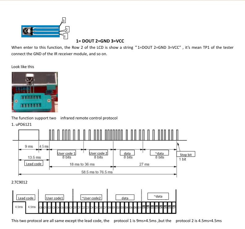
A success decode is list at row4 - 8 of the LCD, where row 4 display the IR protocol (TC9012 or uPD6121), row5 and row6 display “User code 1” and “User code 2” , row 7 display the data and the Bitwise NOT of the data(~data). Row8 is display the four byte together. the hexadecimal system is used to display All of the numbers
IR_Encoder
This function is a simulation of IR Remote Controller. it can drive a IR LED connect at the tester’s PWM output interface associate with the user input . since the tester only provide about 6mA current, the Control distance is less-than a regular IR Remote Controller. On the first column of the LCD , is show a “>” , this symbol can move up or down by a click of the rotary encoder to select a certain item. Row2 of the LCD is select protocol, like IR_Decoder above, there are two protocol for select, ”TC9012” and “uPD6121”. It can be changed by rotate the knob, when the “>” appear at row2. row3 and row4 change the “user code 1” and “user code 2” value by rotate the knob ,left rotate will decrease and right rotate will increase the value . press and hold the knob for >1S and <3S (>3S will exit this function) will add the value by 0x10 to fast reach to the expect value.
Row5 change the “data” ,and the Bitwise NOT of the “data” (~data) is auto calculate by the tester . Row6 ,The “emit:” is used to start a transmit . move “>” to this line, and rotate the knob ,a “->” will appear soon until a transmit complete. This function is “strongly” correlation with the 16.IR_decoder . without decoder ,the value of the user code and data is unknown. Unless you already know them before. Used other methods. The infrared remote control protocol of “TC9012” is frequent use on television in my submission. I think , in china.
C(uF)- correction
This function set the correction value for big capacitor measurement, Positive values will reduce measurement results.
Construction
This is only a partial draft schematic. I mainly used this to record part orientation and interconnection for testing the circuit during construction:

Credits and References
- 2016 DIY kits ATMEGA328 M328 Transistor Tester LCR Diode Capacitance ESR meter PWM Square wave Frequency Signal Generator - from seller on aliexpress
- P6KE6V8 data - parts.io
- HT7750A-1 datasheet
- TL431A datasheet
- SRV05-4 Transient Voltage Suppressors - onsemi, farnell
- My Guide to AVR Transistortesters - by pfred2
- AVR Transistortester - where all these kit designs appear to originate from
- transistortester on GitHub
- ..as mentioned on my blog
