
#273 Voltage Controlled Oscillator
Exploring varicap diodes (KV1471) and their use in frequency tuning of a Colpitts-style voltage-controlled oscillator.
Notes
This project is a study inspired by yet another great video tutorial from w2aew.
It demonstrates how varicap diodes can be used to create a voltage-controlled oscillator.

A varicap diode is type of diode designed to exploit the voltage-dependent capacitance of a reversed-biased p–n junction. This is a feature of all diodes, but is more pronounced in those produced specifically for this purpose. In my version of the circuit I am using the KV1471 diode.
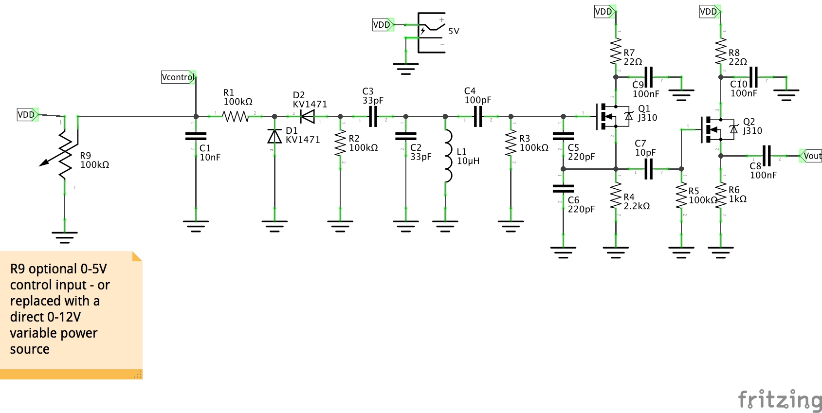
The demonstration circuit is based on a design presented in Chapter 4.6 of Experimental Methods in RF Design.
The basic circuit is a Colpitts oscillator. The varicap diode:
- alters the capacitance of the oscillator and thus the frequency
- has a capacitance inversely-proportional to the applied voltage
- is capacitor-coupled to the oscillator tank so that the varicap voltage does not play a role in the oscillator
- has a back-to-back varicap twin to compensate for rectification effects
Voltage tuning with diodes in circuits such as this can compromise noise and stability, so it is generally recommended to limit the frequency range (capacitance). It is of course possible to adjust the components so that the varicap produces a much wider frequency swing.
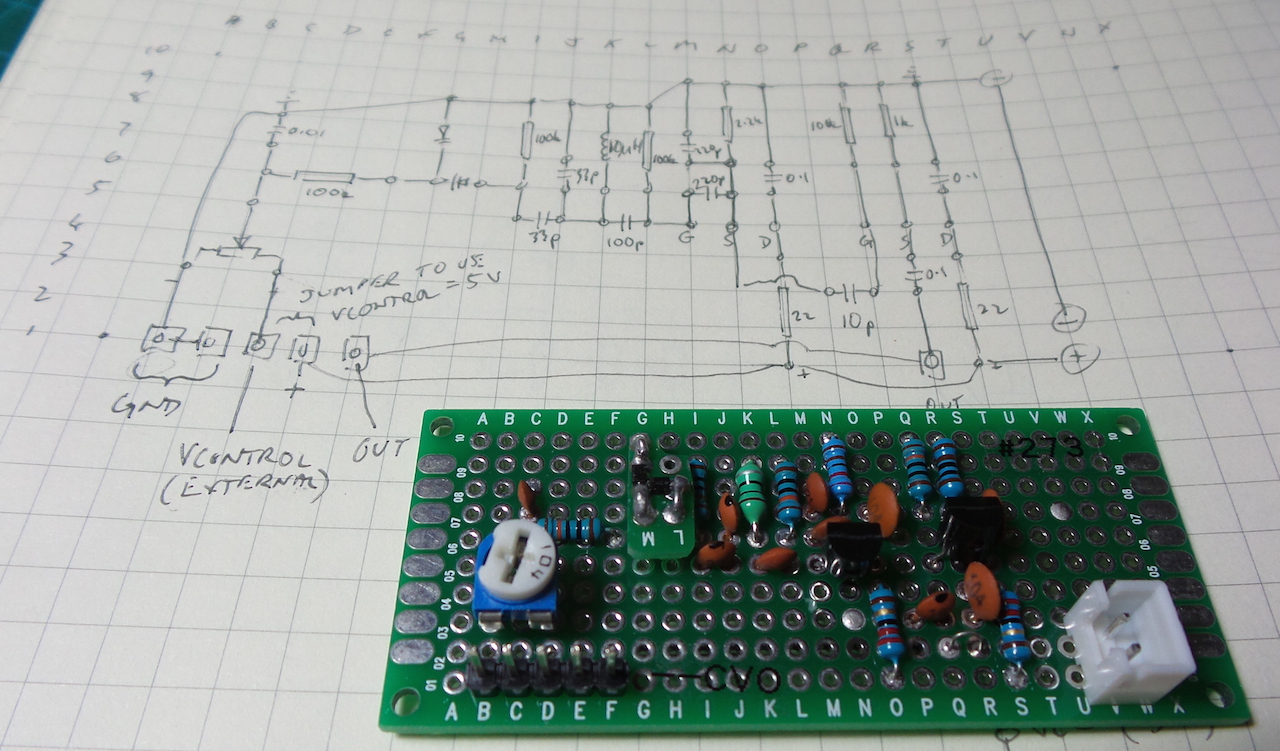
I have the circuit operating on 5V, and by default the varicap voltage is varied from 0-5V with a trim pot. On my protoboard build, I made that jumper-configurable, so an external control voltage can be applied (I tested up to 12V).
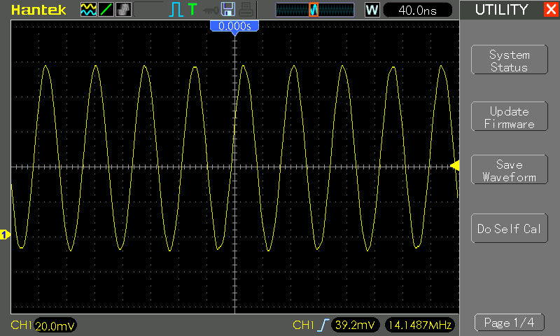
In practice (both on a breadboard for initial tests, and then finally on protoboard) I was unable to achieve the 14MHz oscillation originally intended for this circuit. However by replacing the 1µH inductor with 10µH, I was able to get a nice stable oscillator at 5.46MHz (with no varicap voltage applied), and a varicap tuning range of a quite sizable 0.35MHz.
See below for a section on “Rebuilt for 14MHz” where I tweak the circuit to achieve the originally intended frequency.
Performance
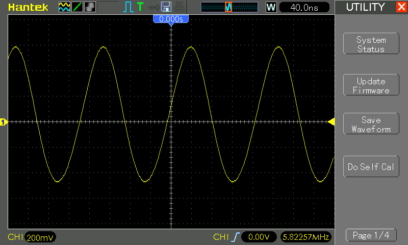
The following scope traces are for the protoboard build.
5.46MHz, with varicap voltage VCONTROL=disconnected (floating):
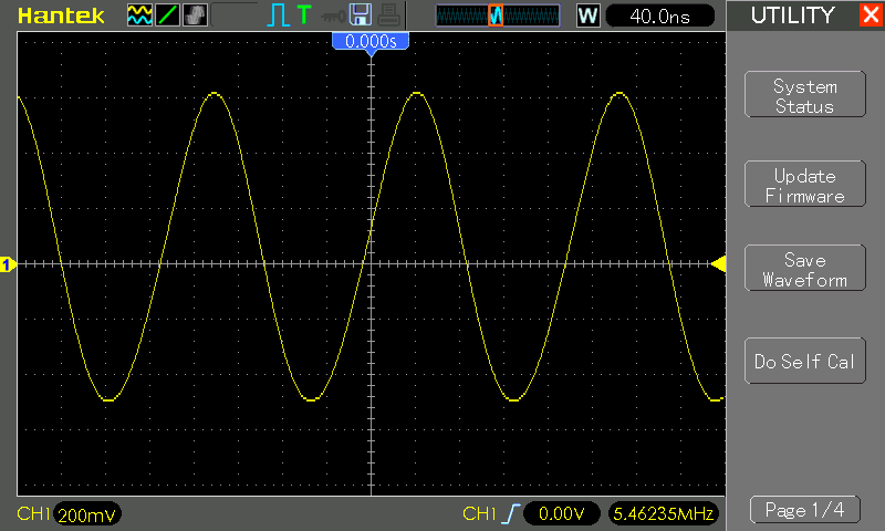
5.45MHz, with varicap voltage VCONTROL=0V:
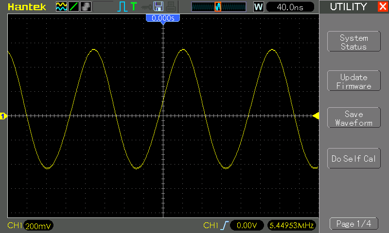
5.80MHz, with varicap voltage VCONTROL=5V:

5.82MHz, with varicap voltage VCONTROL=12V:
Summary of Circuit Variations
These are the critical difference in my circuit tests here from the one used by w2aew and as presented in Experimental Methods in RF Design:
| Item | Original | As Used Here |
|---|---|---|
| D1, D2 Varicap | BB104/MV104 | KV1471 |
| L1 Inductor | 1µH wound toroid | 10µH RF choke |
The other main difference (which I’m sure limits the frequency I could achieve) is construction:
- In Experimental Methods in RF Design, they describe a circuit mounted in a 1590A (metal I presume) enclosure with coaxial output
- w2aew used Manhattan-style construction on a solid copper PCB ground plane
I have just used:
- breadboard for initial tests
- protoboard for final tests, but it lacks a decent groub plane and was not enclosed or shielded.
Rebuilt for 14MHz
I wondered if breadboard/protoboard construction was preventing me from achieving the originally-intended 14MHz. I rebuilt the circuit on copper PCB Manhattan-style but this quickly confirmed the issue was really more about component selection than construction.
I should have compared the varactors more closely. The KV1471 I’m using has a much lower capacitance range than the MV104 used in the original circuit, and the MV209 as used by w2aew.
- KV1471 7.7pF at 4.5V to 35.6pF at 1V reverse voltage
- MV104 35pF to 60pF (per capacitor) for a similar reverse voltage range
- MV209 22pF to 50pF for a similar reverse voltage range
So I now have a 14MHz VCO with a few more component changes (with respect to the schematic below for my first build):
| Item | Per Schematic | Replacement |
|---|---|---|
| L1 Inductor | 10µH RF choke | 2µH RF choke |
| C3 Capacitor | 33pF | 5pF |
| C2 Capacitor | 33pF | 4pF |
Here it is on a PCB. Note that I used some female pin headers so I could easily experiment with alternative L1, C2, C3 component selections.

With 0V applied to Vcontrol, the operating frequency is 14.15MHz:
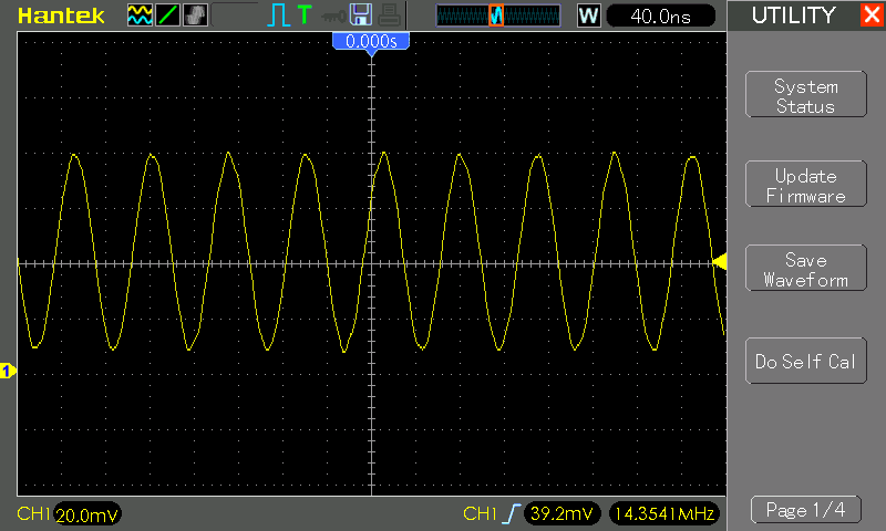
With 5V applied to Vcontrol, the operating frequency rises to 14.35MHz:
Note that at 14MHz, the output signal is significantly attenuated compared to my first 5MHz build. This could probably be improved by also revising some of the FET biasing. Job for another day…
Construction
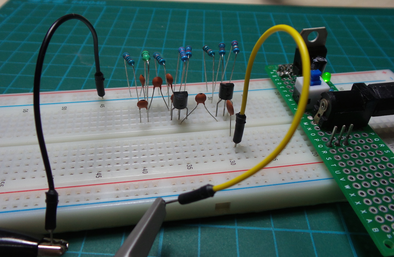
I used the breadboard to first make sure I could get a good oscillation. Shown here without the varicaps installed:
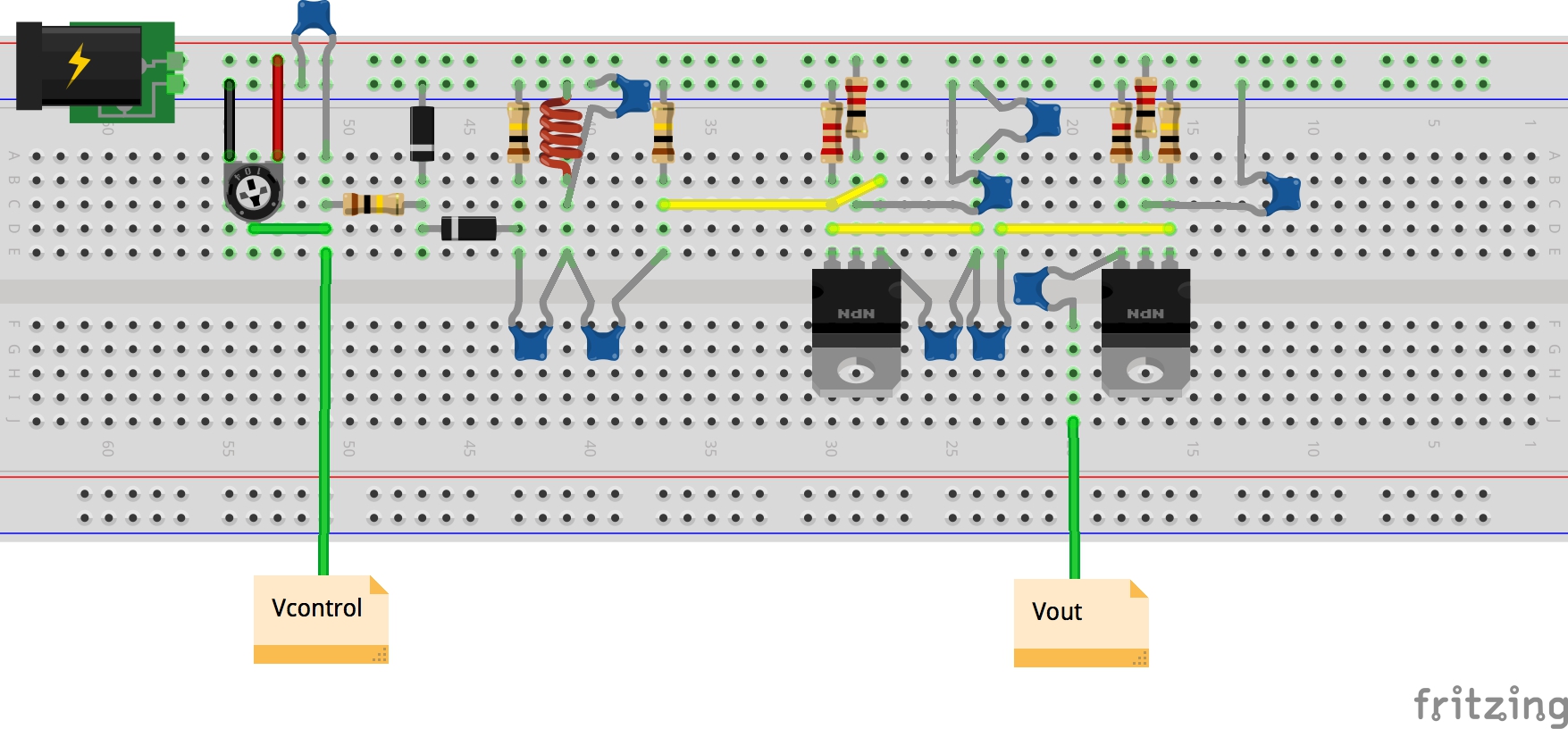
The protoboard layout is shown here. Since I have KV1471 diodes in surface-mount packages, I had first mounted them on a fragment of protoboard and made it breadboard pluggable. In the protoboard version, I’d just soldered it directly in.
The pin header provides convenient access to (from left to right):
- ground
- ground
- vcontrol (for external vcontrol power supply)
- VCC/5V (so it can be jumpered to vcontrol)
- output
Credits and References
- #147: Basics of Varactor Diodes - Voltage Controlled Oscillator VCO Example - from w2aew
- w2aew’s notes
- Varicap - wikipedia
- Varicap, Varactor Diode circuit demo - AllAmericanFiveRadio
- Experimental Methods in RF Design
- KV1471 datasheet
- J310 datasheet
- MV104 datasheet
- MV209 datasheet