
#857 Ultrasonic Piezo Polarity Tester
Using an Arduino to automatically determine the polarity of ultrasonic piezo transducers.
Here’s a quick demo..
Notes
Ultrasonic piezo transmitters and receivers such as the TCT40-16 are inherently polarized. Correct polarity may be significant depending on the application. See LEAP#856 TCT40-16 for more details.
While a simple multimeter test can usually determine polarity, this project expands on an idea found at https://www.instructables.com/Acoustic-Levitator/ to create an automated test bed powered by an Arduino.
The project relies on the fact that when sampling the voltage:
- if the piezo anode is sampled with piezo cathode connected to ground: the voltage will steadily rise
- if the piezo cathode is sampled with piezo anode connected to ground: the voltage will always be ~0V
- if there is no piezo connected to the sampling pin: the voltage will fluctuate randomly
Some caveats:
- I’ve noticed the behaviour can be quite erratic if powered from a noisy power supply (e.g. a wall wart) or under-powered power bank.
- Generally works perfectly if powered from my computer USB.
- If don’t get a clear reading at first, can help to flip and retest the piezo orientation a few times until it “settles” on a stable behaviour
Circuit Design
Designed with Fritzing: see PiezoPolarityTester.fzz.
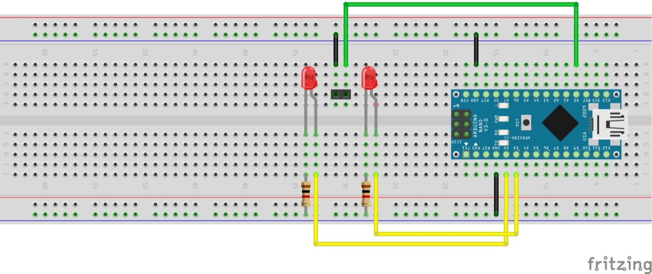
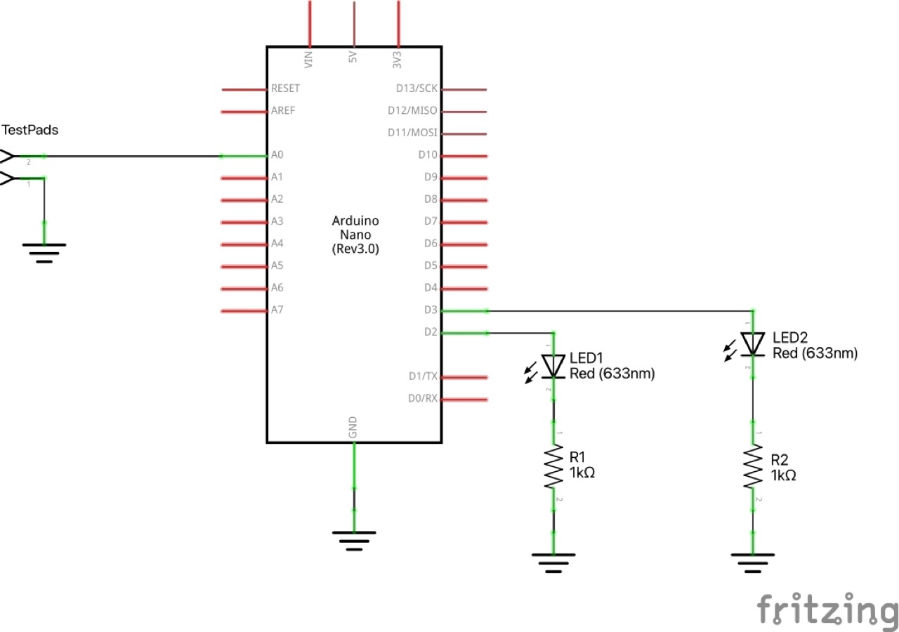
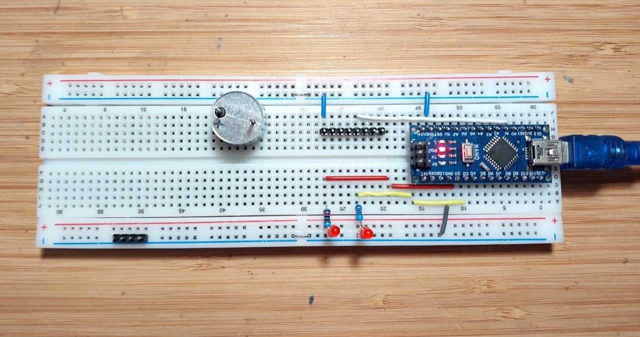
Setup for testing on a breadboard:
The Sketch
Some points to note:
- I am using an Arduino Nano here, but any Arduino model would work just as well
- it sets the ADC sampling rate to ~9.6KHz
- ADCSRA register is setup with ADC prescaler of 128
- with 16MHz clock in the nano, this sets ADC Clock Frequency to 16MHz/128 = 125kHz
- 13 ADC clock cycles are required to complete one conversion, so sampling rate is 125kHz/13 ~= 9615Hz
- it uses a rough variance calculation to determine the polarity:
- takes 5 readings, each reading is the average of 32 samples
- calculates the average variance from one reading to the next
- categorizes the result:
- very low variance: piezo is inverted
- moderate variance: piezo is not inverted
- high variance: probably no piezo connected
- sets the LEDs accordingly:
- both off: no piezo detected
- will light the LED matching the positive terminal (anode) of the piezo
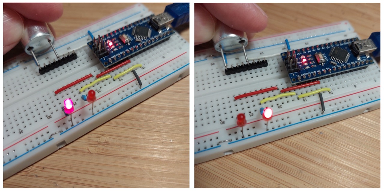
Breadboard Test
Works nicely with a reliable indication of which terminal is positive.
Protoboard Build
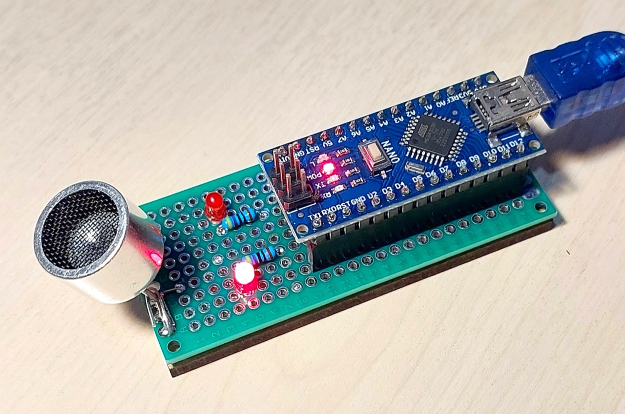
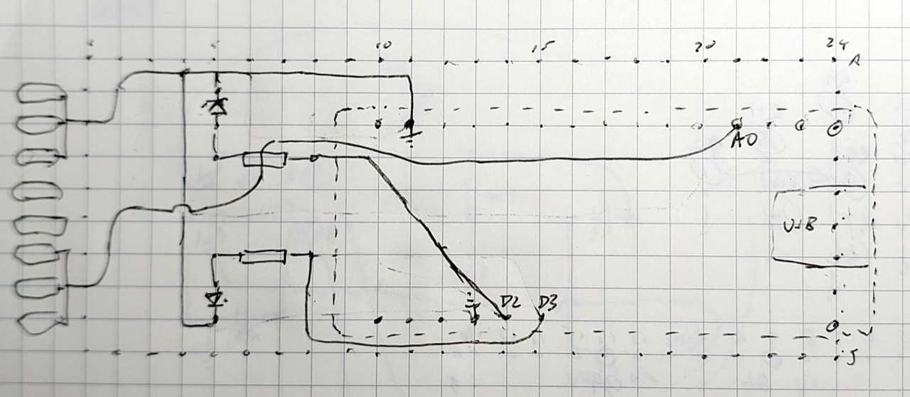
To make it a little more convenient to use, I transferred the circuit to a small 3x7cm protoboard. I planned out a rough layout:
As built. I fashioned clips from some component leads to “spring-load” the piezo under test.
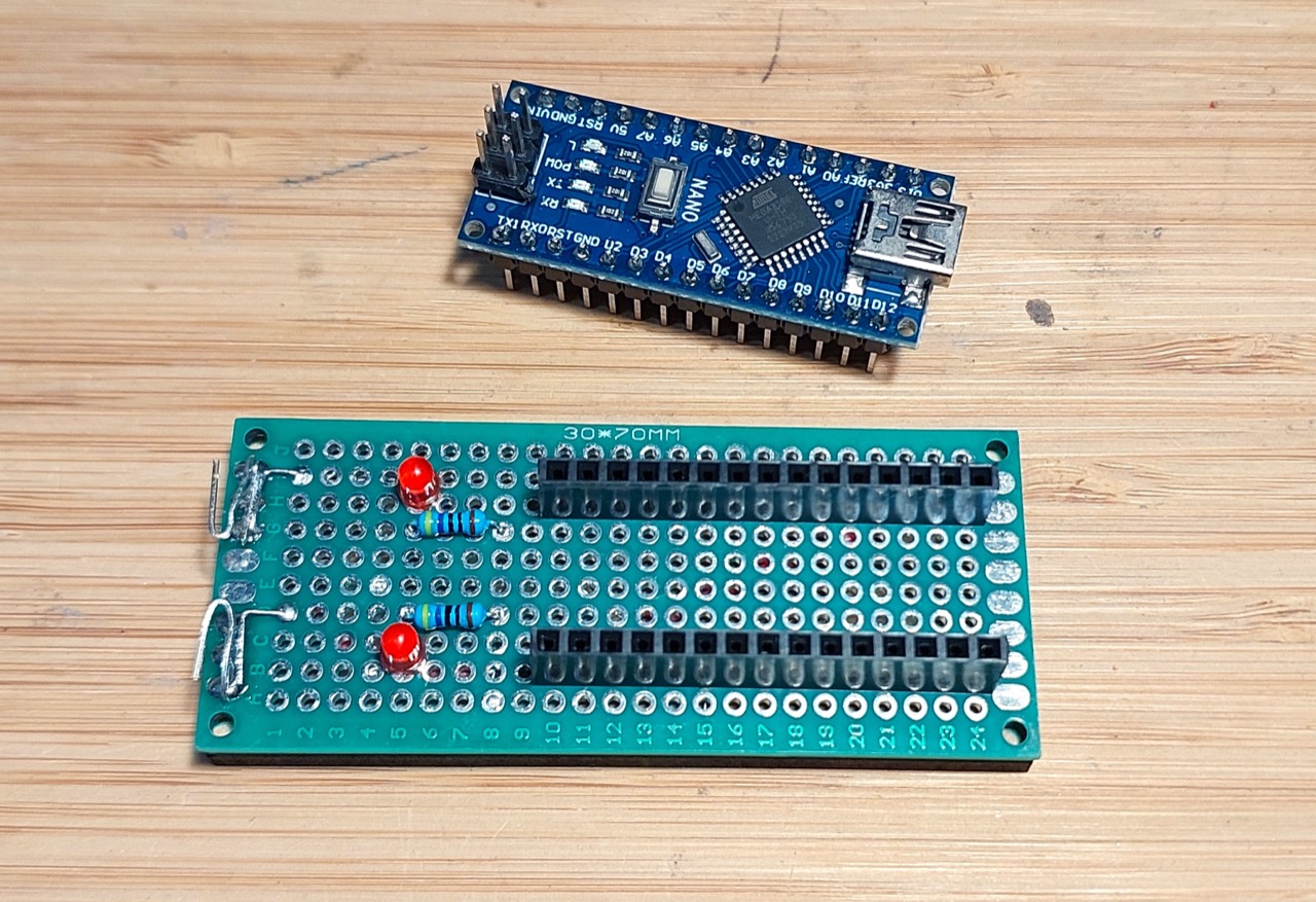
I stuck the board to a 3x7cm piece of 3mm MDF with hot glue to protect the underside from shorts and make it sit on a bench nicely.
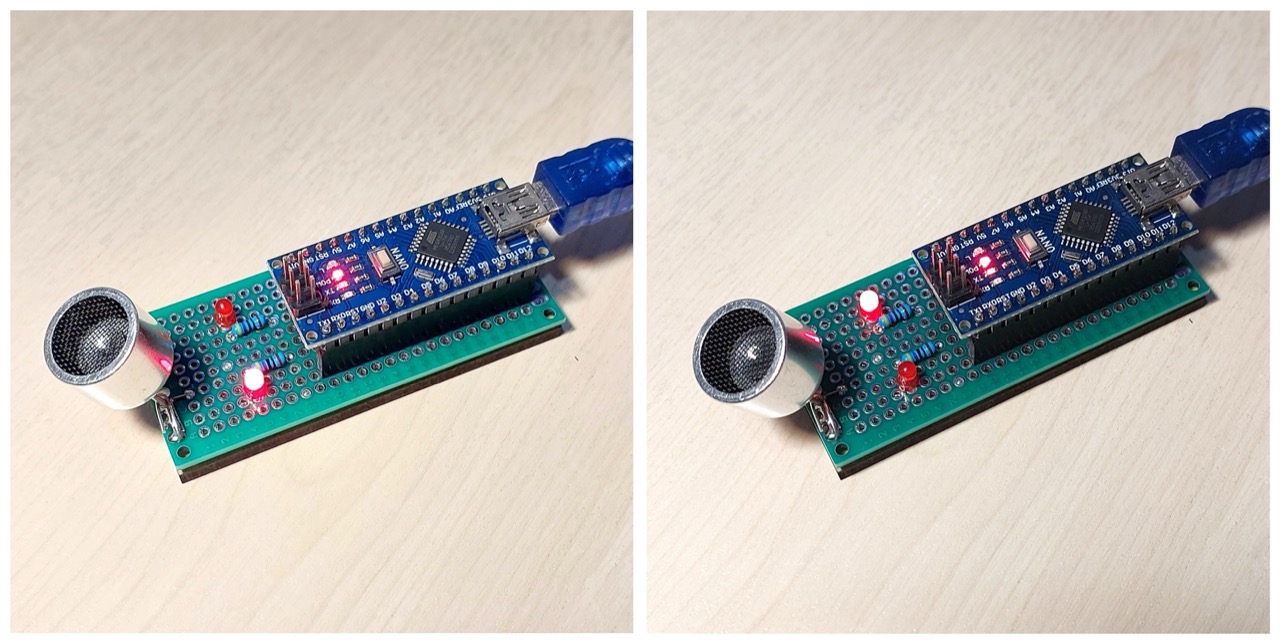
Under test:
Credits and References
- https://www.instructables.com/Acoustic-Levitator/ - source of the original idea
- LEAP#856 TCT40-16