
#413 Incremental Rotary Encoder Tester
Demonstrating a rotary encoder forward/reverse LED indicator using simple digital logic.
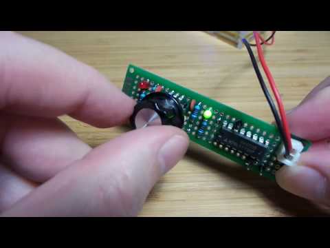
Here’s a quick demo..
Notes
Incremental Rotary encoders typically provide quadrature output on two pins:

LEAP#118 RotaryEncoderMethods demonstrates various ways of using a rotary encoder with an Arduino, but I’m inspired to throw away the microcontroller for a more basic demonstration after reading Experiment 101: Rotary Encoders from ARRL Hands-on Radio (Vol 2).
This project demonstrates a forward/reverse LED indicator using simple digital logic and a mini rotary encoder (from seller on aliexpress).
Design
Key thing to note from the quadrature diagram:
on the edge of one output from the rotary encoder, the level of the other output will indicate whether rotation is forward or reverse
This insight is used by Experiment 101: Rotary Encoders, where one signal is considered a clock source and the other the data to be latched with a CD4013 D-type flip-flop. The output controls a “forward” LED, and the complementary output drives the “reverse” LED.
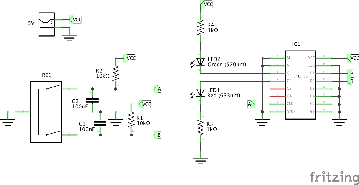
I don’t have any CD4013 on hand, so modified the idea to work with 74LS173. The 74LS173 is a 4 bit D latch and doesn’t have complementary outputs, so in this design it uses two of the D latches - one configured to drive the “forward” indicator, the other for the “reverse”. The 74LS173 can source/sink enough current to drive and LED at under 5mA in either direction.
The 74LS173 clocks on the rising edge
| CL | -G0 | -G1 | CLK (A) | D (B) | Q | Inferred Rotation |
|---|---|---|---|---|---|---|
| 0 | 0 | 0 | rising | 0 | 0 | CW |
| 0 | 0 | 0 | rising | 1 | 1 | CCW |
There are may other ways of achieving this. For example one other alternative I scoped out was using a 74LS73 JK Flip-flop and an inverter.
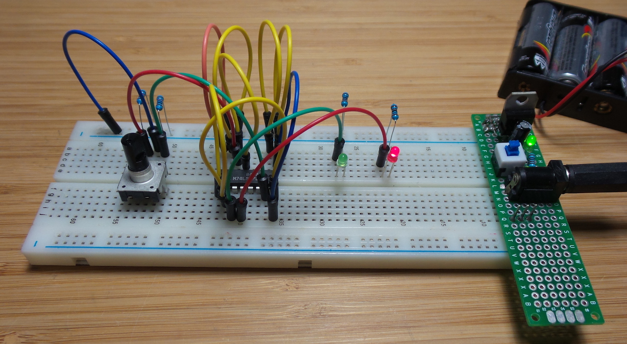
Construction
I tested this out on a breadboard first. The 100nF capacitors coupled with the 10kΩ pull-up resistors on the A/B rotary encoder connections are for hardware de-bouncing.
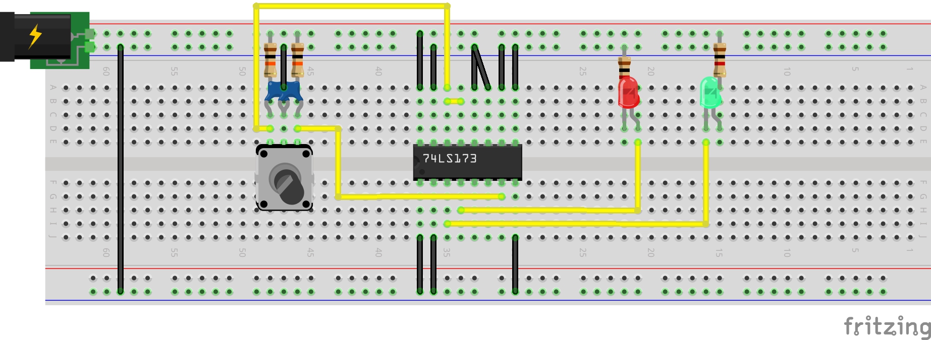
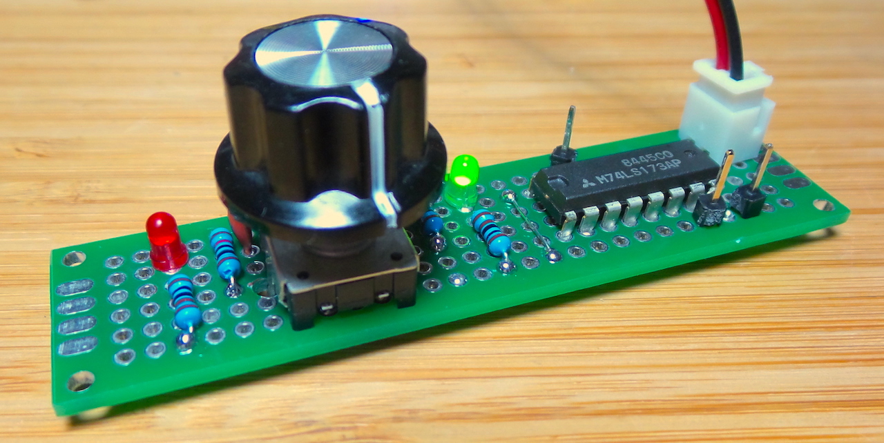
But then decided to capture the circuit on protoboard using this layout:
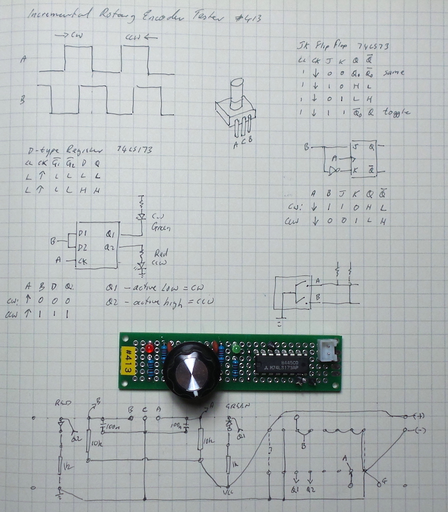
The final protoboard build:
Testing
I added pin headers to the protoboard to assist capturing signals with a scope. Here are some traces where:
- CH1 (yellow) - CLK (A)
- CH2 (blue) - D(B)
Here’s a clockwise (CW) rotation capture. Note the effectiveness of the hardware de-bouncing - quite clean transitions.
Here’s a counter-clockwise (CCW) rotation capture:
Credits and References
- Rotary_encoder - wikipedia page
- 74LS173 datasheet
- JK flip-flop - wikipedia
- mini rotary encoder from seller on aliexpress.
- ..as mentioned on my blog