
#337 RGB LED Glow Effects
Rainbow glow effects with an RGB LED and OpAmp oscillators.
Notes
For a while I’ve been thinking of ways to generate a pseudo-random rainbow glow on a composite RBG LED. In particular, by avoiding just throwing a microprocessor at the problem!
First, I want a waveform that has a smooth rise and fall in intensity, including being off for a period. Second, the reg, green, blue waves should not be synchronised, so the effect is an infinite colour palette.
I finally settled on three independent opamp-based triangle wave generators.
RGB LEDs
The RGB LEDs I have are common anode:
- Size: 5mm
- Pins sequence: RED/Common Anode(positive terminal)/Green/Blue
- View Angle: About 25 degree.
- R: wavelength 630-640nm, Brightness 1000-1200mcd, Forward Voltage 1.8-2.0V
- G: wavelength 515-512nm, Brightness 3000-5000mcd, Forward Voltage 3.2-3.4V
- B: wavelength 465-475nm, Brightness 2000-3000mcd, Forward Voltage 3.2-3.4V
Basically, these are just three LED dies in the one package.
Triangle Wave Generator
I borrowed the basic idea from Breathing Lamp Effect, and adjusted the components for best effect.
The three oscillators are independent and nominally run at the same frequency. But component tolerances introduce enough variation that the phase difference of the three oscillators drift slowly, resulting in a continually varying mix.
A common reference voltage sets the feedback offset. This is adjustable, the effect being to shift the waveforms with respect to the required LED control levels (meaning the LEDs stay on for longer of shorter periods).
Here’s a sample of the Red (CH3), Green (CH1), Blue (Ch2) waveforms.
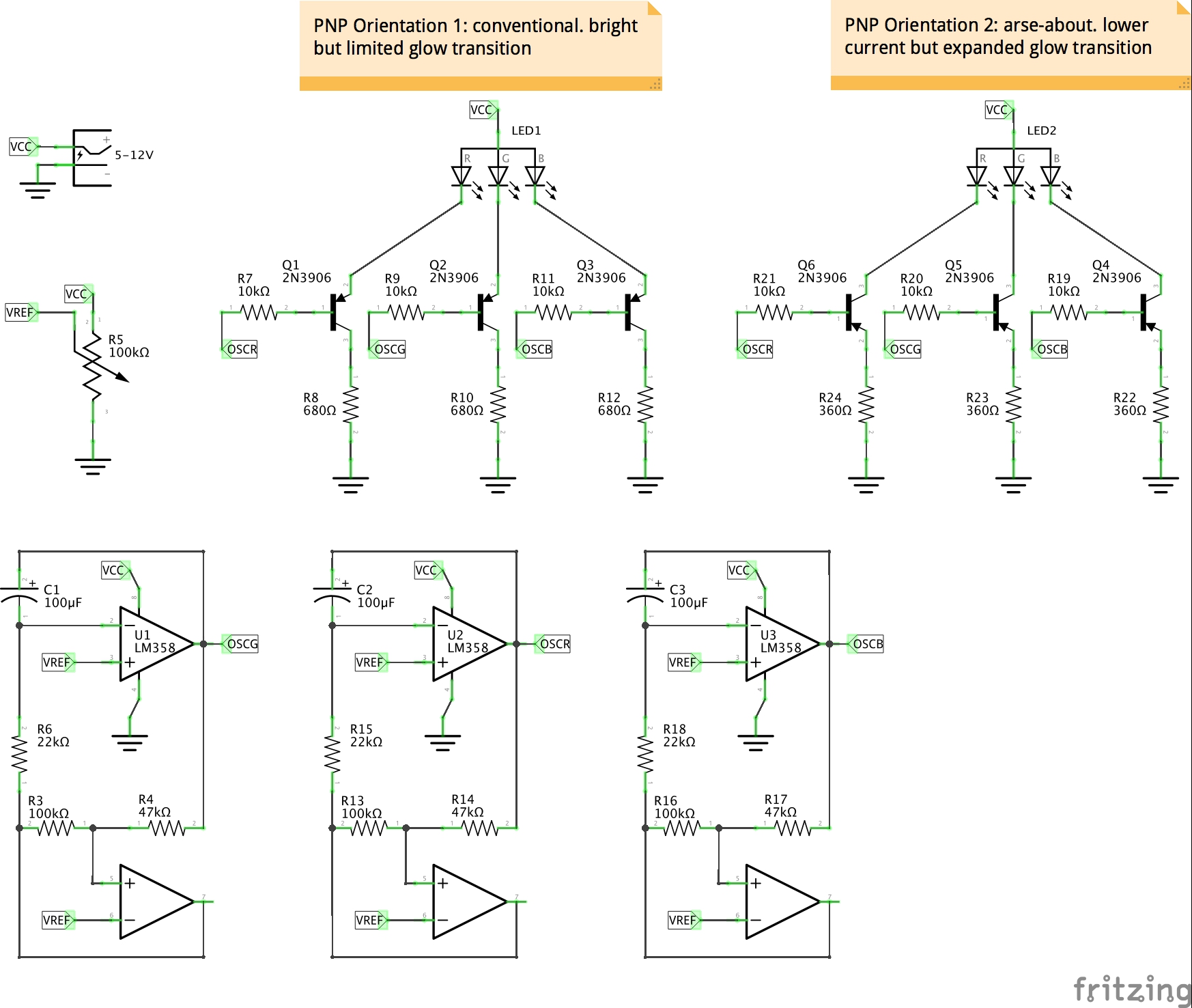
LED Control
The LEDs are configured with a low-side PNP control and current-limiting resistors. This puts the linear region of the transistors in the general vicinity of the triangle waveforms.
After some experimentation, I discovered I could get a much more pleasing “glow” effect by reversing the PNP driver transistors (i.e. swap Collector and Emitter). The current flow is reduced, which can be offset by also reducing the current-limiting resistors. But it does expand the (pseudo-)linear region to cover the entire triangle wave sweep. This is a bit of a hack, and could probably be better achieved by ensuring the driving triangle wave is amplified and offset precisely to bias the transistors appropriately.
The schematic shows the alternative arrangements. The demo video is using the reversed-PNP arrangement.
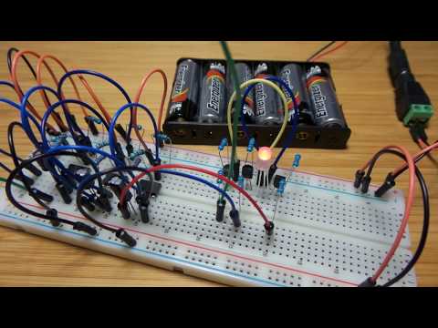
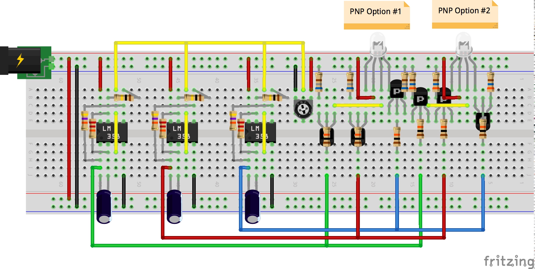
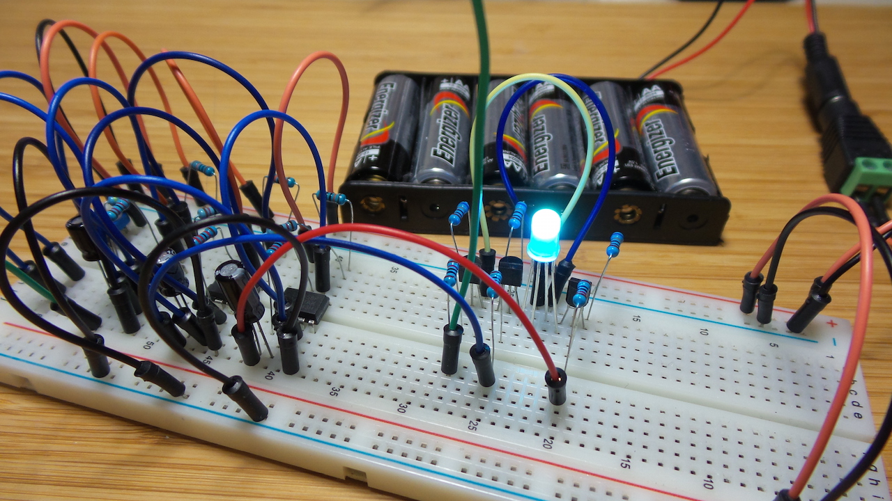
Construction
Credits and References
- RGB LED datasheet
- LM358N Datasheet
- RGB LED - aliexpress seller
- Breathing Lamp Effect
- ..as mentioned on my blog