#642 MT3608 Safe Control
Configuring variable boost control with the MT3608 that is safe for all rated input voltages.

Notes
Many of the circuits one will find for the MT3608 use simple voltage divider with a variable resistor for R1 and a fixed R2. This was the case in LEAP#570 and with most of the commonly available MT3608 modules.
These make for cheap circuits, but what may not be obvious is that in most cases the circuit is design for and assumes an input voltage of 5V or lower. If higher voltages are applied then it is possible to take the FB pin above its 6V rating and potentially damage the MT3608 chip.
While one can design for specific input voltages, the circuit presented here is an attempt at a “general purpose” circuit that can:
- support the full input voltage range allowed by the MT3608 (2 to 24V)
- support up to the full output voltage allowed by the MT3608 (28V)
- ensure FB voltage can’t exceed the 6V max rating
Calculations
The feedback voltage-divider with two resistors establishes the output voltage level where Vref is 0.6V:
Vout = Vref * (1 + R1/R2)
How the Simple R1/R2 Design Performs
A common configuration is R1 = 100kΩ pot, R2 = 2.2kΩ.
Here are the design results with R1 at it’s midpoint and extremes. As is pretty clear, as R1 approaches 0, then the voltage at the FB will approach Vin. So as long as Vin is below 6V then we can keep V(FB) within spec:
| R1 | R2 | Vout | V(FB) at VIN=2V | V(FB) at VIN=5V | V(FB) at VIN=24V |
|---|---|---|---|---|---|
| 0 | 2.2 | 0.6* | 2 | 5 | 24 |
| 50 | 2.2 | 14.24 | 0.08 | 0.21 | 1.01 |
| 100 | 2.2 | 27.87 | 0.04 | 0.11 | 0.52 |
- actually would be Vin less 1 diode drop
Revised Design
The voltage at the FB pin will be Vout * R2/(R1+R2) thus we alway need R1 to be large enough to keep the result below 6V.
R2 will also need to stay out of the region that would be trying to push the output above the rated 28V.
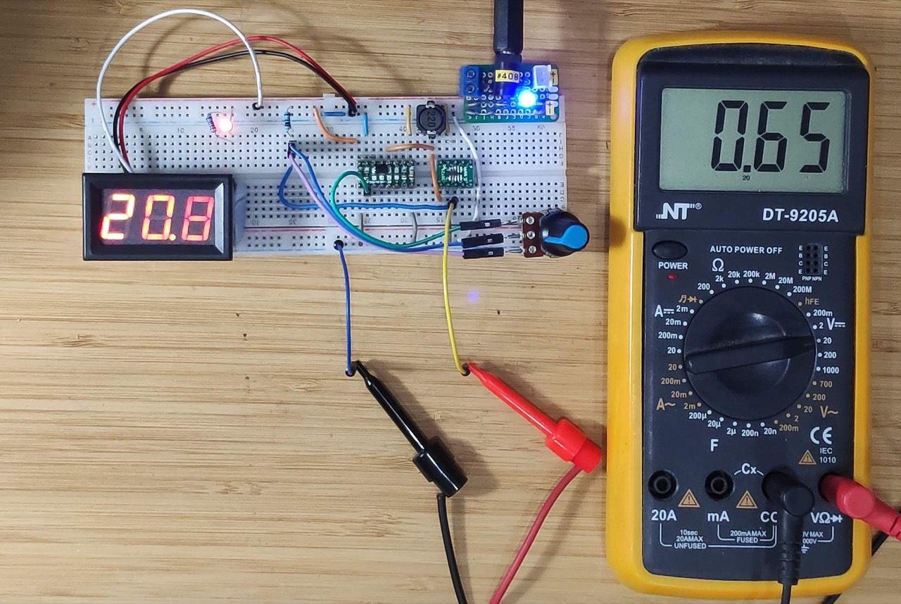
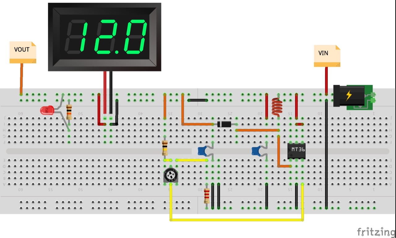
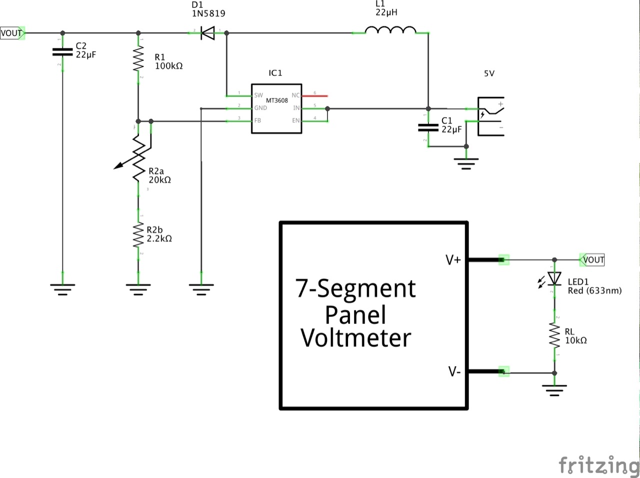
One solution is to put the variable resistor (“rheostat” wiring) in R2 along with a small fixed R2 component. There is a set of simultaneous equations that could be written to find the best values, but I just spent a few minutes in a spreadsheet to come up with these values that seem to work reasonably well:
- R1 = 100kΩ
- R2a = 20kΩ pot
- R2b = 2.2kΩ
Here are the design results with the pot at it’s midpoint and extremes.
The feedback voltage V(FB) will be kept at the nominal 0.6v (Vref) by the MT3608. The V(FB) calculations are the worst case assuming Vout = Vin(max), ignoring the diode drop.
| R1 | R2 | Vout | V(FB) at VIN=2V | V(FB) at VIN=5V | V(FB) at VIN=24V |
|---|---|---|---|---|---|
| 100 | 2.2 | 27.87 | 0.04 | 0.11 | 0.52 |
| 100 | 12.2 | 5.52 | 0.22 | 0.54 | 2.61 |
| 100 | 22.2 | 3.30 | 0.36 | 0.91 | 4.36 |
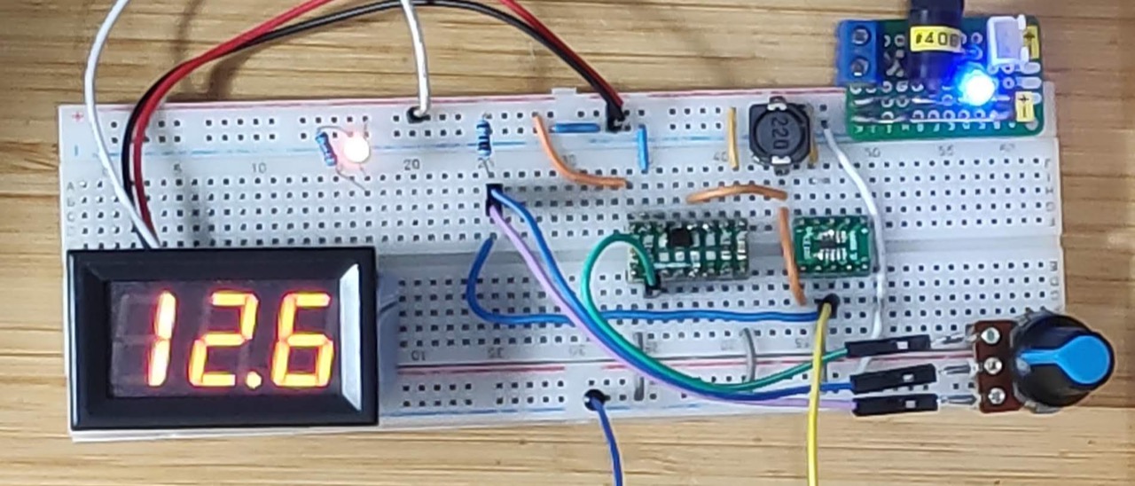
So with this configuration we can access a full output range up to 27.9V and use any input voltage from 2 - 24V without risking V(FB) exceeding 4.5V. Job done, with just 1 extra component required.
Construction


Credits and References
- MT3608 datasheet
- 1N5819 Datasheet
- LEAP#570 MT3608 on a Breadboard
- Having problems with a step up converter - eevblog
- MT3608 problems
