Fork me on GitHub

Project Notes

#183 Polarity Tester

Demonstrate a polarity-testing circuit using the CD4069 inverter.

The Build

Notes

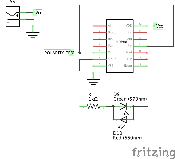
A simple polarity testing circuit uses a series of inverters. The input signal is pumped into two parallel chains:

  • a single inverter
  • a series of two inverters

So, regardless of input polarity, one chain output will be high and the other low.

input Single-inverter Output Dual-inverter Output
LOW HIGH LOW
HIGH LOW HIGH

The signals are tied together with two reverse-polarity LEDs in series. So one will always be alight when the other is not. The unlit LED is subject to a reverse voltage equivalent to the forward voltage of the other LED. Most LEDs will handle this without complaint.
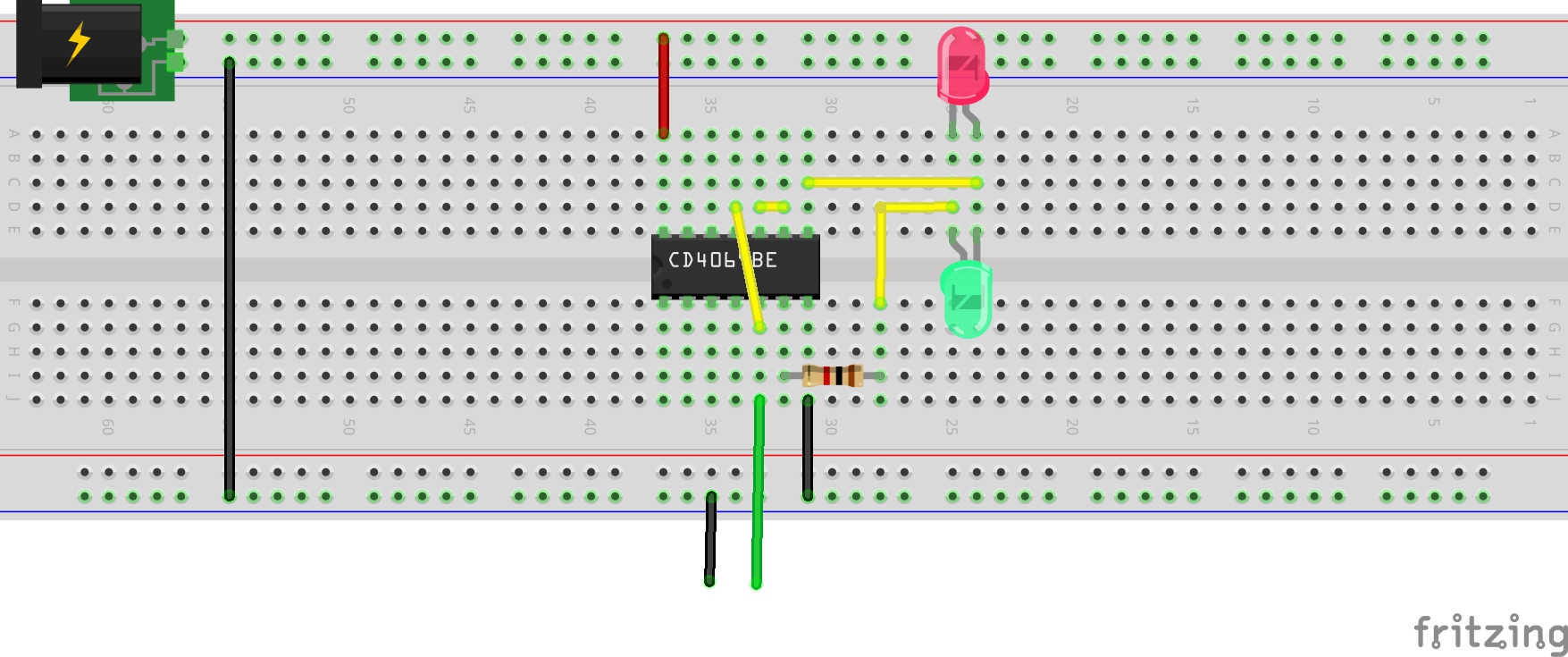
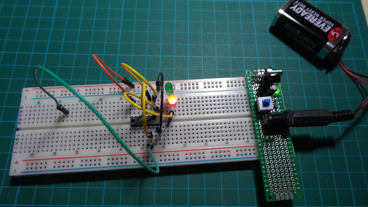
Construction

Breadboard

The Schematic

The Build

Credits and References

About LEAP#183 CMOS/TTL
Project Source on GitHub Return to the LEAP Catalog

LEAP is just my personal collection of electronics projects - usually involving an Arduino or other microprocessor in one way or another. Some are full-blown projects, while many are trivial breadboard experiments, intended to learn and explore something interesting.

Projects are often inspired by things found wild on the net, or ideas from the many great electronics podcasts and YouTube channels. Feel free to borrow liberally, and if you spot any issues do let me know (or send a PR!). See the individual projects for credits where due.

For a while I have also included various scale modelling projects here too, but I've now split those off into a new repository. Check out LittleModelArt if you are looking for the modelling projects!

Project Gallery Notebook LittleCodingKata LittleModelArt More on my blog