#144 Ring Oscillator
Test a ring oscillator built with a 74LS14 Inverter chip

Notes
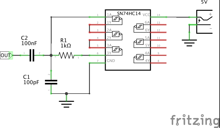
A Ring Oscillator is constructed with an odd number of inverters in series, with the output feeding back to the input.
Since an odd number of inverters, the output is logically the complement of the input. This conflict results in oscillation.
The frequency of oscillation is governed by the inherent propagation delay of the inverter:
f = 1 / (2 * t * n)
Where:
2 : since two oscillations make a complete cycle
t : propagation delay of a single inverter
n : number of inverters
The propagation delay is subject to a range of instabilities:
- jitter (noise)
- temperature
- voltage
The frequency of the oscillator may be controlled in a number of ways:
- vary voltage within the limits supported by the inverter
- add more inverters to the ring
- add an RC network to the circuit to further slow the oscillation according the the RC time constant
Test Results
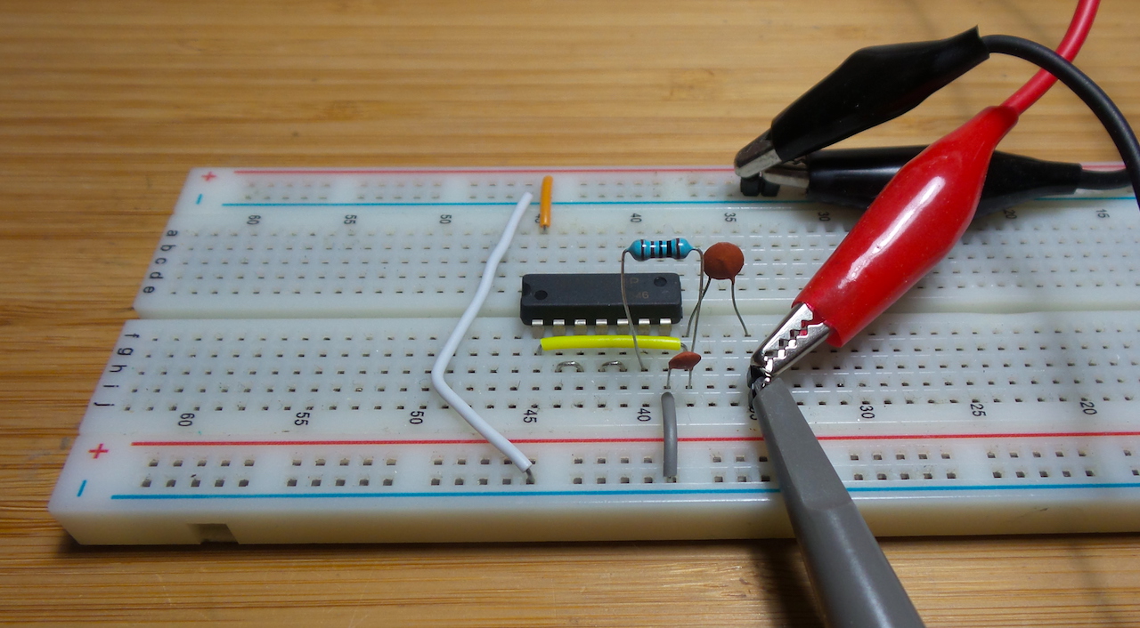
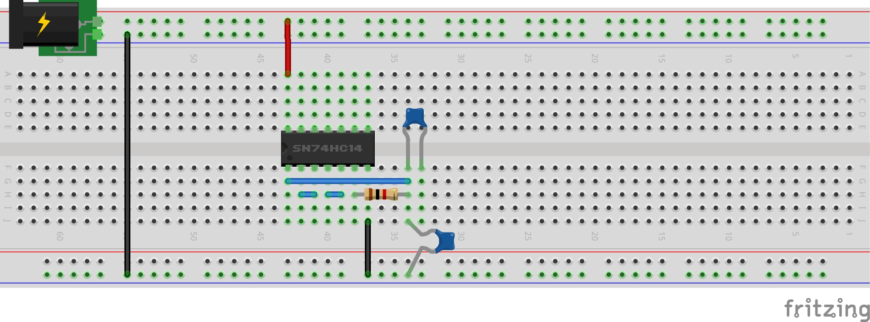
The demo circuit is built with 3 inverters in a 74LS14 chip. An RC network is added to the output to test control of the oscillation.
The follow table lists my frequency measurements with various resistor/capacitor values.
| R1 | C1 | Frequency |
|---|---|---|
| c/c | o/c | 11502 kHz |
| 1kΩ | o/c | 1860 kHz |
| 1kΩ | 100pF | 1302 kHz |
| 1kΩ | 1nF | 547 kHz |
| 1kΩ | 10nF | 87 kHz |
| 1kΩ | 100nF | 9.3 kHz |
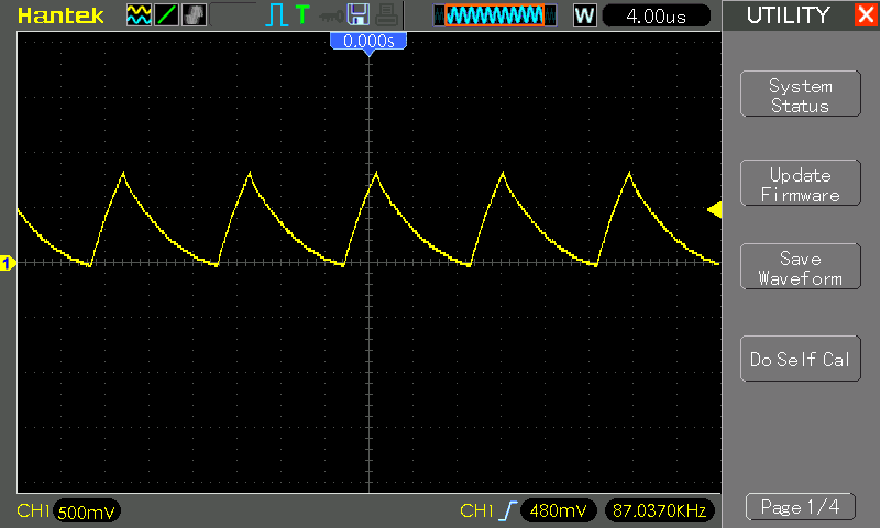
Here’s an example waveform (10nF case):

Using a 74HC14
A 74HC14 can be used in the circuit, however:
- R1 needs to be increased significantly in order to oscillate: at least 10kΩ, 100kΩ
- frequency stability is very poor compared to 74LS14
Construction


Credits and References
- Ring Oscillator - wikipedia
- 74LS14 Datasheet
- 74HC14 datasheet
