#142 High-frequency OpAmp Oscillators
How fast can you push an Op-Amp oscillator?
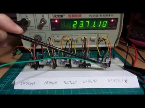
Here’s a quick demo of the circuit in action:
Notes
I’ve previously wired up a classic single-rail op-amp oscillator in the LEAP#039 Astable Opamp Oscillators project, but this was running at very low frequencies, and its behaviour matched the theory quite closely.
The essence of an op-amp oscillator is to use an RC circuit to throw an op-amp comparator from one rail to the other. There are many sources on the net describing the technique (here’s a good one). A ballpark approximation of the frequency is obtained with the formula:
f = 1 / ( 2 * ln(2) * R * C )
This is derived from the RC complete response formula. The initial doubling ( 2* ) is to account for the full cycle. The real fudge is the ln(2) factor. This really depends on the resistors used to bias the non-inverting input, and the upper and lower saturation voltages.
Recently I’ve been wanting to experiment with op-amp oscillators running at higher frequencies, and rudely discovered what most must already know: actual performance at higher frequencies can be a far cry from theory. Now I don’t feel half so bad about the ln(2) approximation!
It appears that once you get into these higher frequencies - admittedly, not very high in the scheme of things - the characteristics of the actual op-amp chip overshadow any predictions you might make on the basis of RC theory and ideal op-amp behaviour.
Key measures are bandwidth gain product (unity gain) which indicates the frequency at which gain drops below unity (and generally rapidly tailing off), and slew rate, which is an indication of how fast the chip can switch its output.
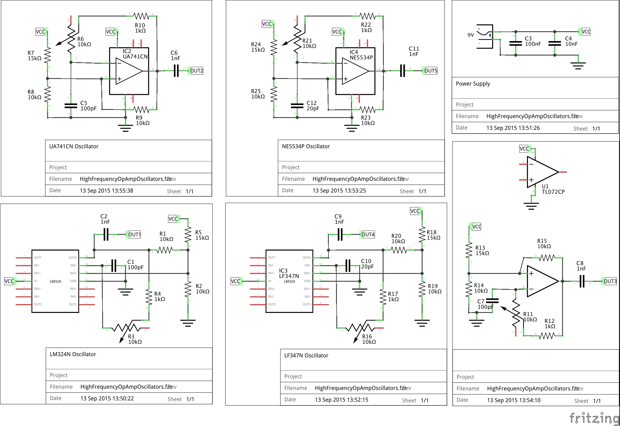
Here is the basic oscillator circuit in CircuitLab, in this case the 741 version:
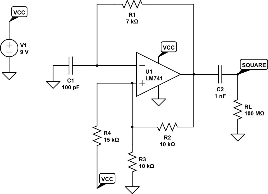
Some things to note:
- R2, R3 and R4 set the reference voltage bias. Note that it is slightly asymmetrical, to account for the fact that these op-amps don’t swing rail-to-rail.
- C2 removes the DC-offset on the output
- R1 and C1 set the timing of the oscillator. In the circuits built for testing, R1 is a combination of fixed and variable to allow tuning of the oscillation frequency
- time domain simulation in CircuitLab doesn’t appear to be particularly accurate either, as it appears to assume much better rail-to-rail performance than is achieved in practice
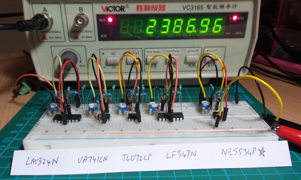
In the following table I summarise the highest stable frequency I was able to achieve in a breadboard test of 5 chips. I could push some quite a bit higher, but oscillation rapidly started to become unstable and eventually dropped back off.
This is not a perfect test by any means:
- I don’t have QA certification for any of the chips tested
- the breadboard brings its own issues of stray capacitance and imperfect connections
- these are all quite old op-amp designs; there are many newer chips that should drastically outperform this set
- these are measured with a frequency counter and I don’t have a scope available to inspect the waveforms. I may have made some fundamental measurement mistakes, and ended up measuring a harmonic instead of the fundamental frequency for example.
| OpAmp | Unity Gain | Slew Rate | Max Stable Freq | R1 at max freq | C1 |
|---|---|---|---|---|---|
| LM324N | 1.2 MHz | 0.5 V/µs | 229 KHz | 3.82kΩ | 100pF |
| UA741CN | 1.5 MHz | 0.5 V/µs | 206 KHz | 7.13kΩ | 100pF |
| TL072CP | 3 MHz | 13 V/µs | 220 KHz | 4.35kΩ | 100pF |
| LF347N | 4 MHz | 13 V/µs | 1.307 MHz | 2.75kΩ | 20pF |
| NE5534P | 10 MHz | 13 V/µs | 2.371 MHz | 1.63kΩ | 20pF |
The only real surprise here is the TL072CP; I should be able to get much better performance from it. Maybe the components I have on hand are not up to normal spec: purchased online from one of the marketplaces, so always a chance these are “failed QA” rejects.
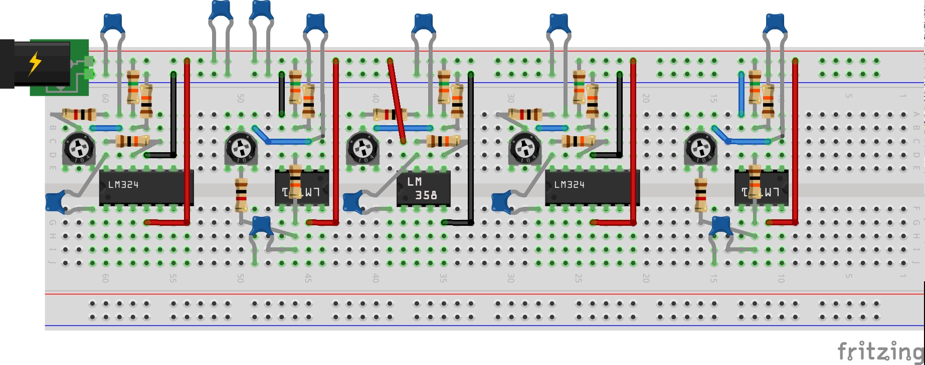
Construction