
#335 MCP2200 Chaser
Using the MCP2200 GPIO from MacOSX. With great power comes great responsibility to blink LEDs.

Here’s quick demo to show it in action:
Notes
The MCP2200 has 8 GPIO pins that can be used for digital input and output. Four of the pins have alternative functions which may render them unavailable.
But GPIO on a USB to UART chip?? Perhaps a few reasons:
- for control signals to the attached device (like toggle a reset line)
- for building USB gizmos
I think I’ll do the later;-)
Using the GPIO pins
The I/O pins actually have decent current handling capabilities, from the datasheet:
- Maximum output current sunk or sourced by any I/O pin: 25 mA
- Maximum current sunk or soruced by all ports: 90 mA
Using the GPIO pins for digital output involves two HID commands.
- CONFIGURE: set pin mode in IO_bmap, and
- SET_CLEAR_OUTPUTS to set or clear pin states
Using the GPIO pins for digital input involves two HID commands.
- CONFIGURE: set pin mode in IO_bmap, and
- READ_ALL to get the IO_Port_Val_bmap values
A Chaser Demo
To test the I/O capabilities, I decided on a simple chaser that employs all 8 GPIO pins:
- GP0 is an active-low input tied to a pushbutton with pull-up resistor and a little RC de-bouncing
- GP1-7 are outputs that control a series of LEDs (configured as active-low, although it could just as well be the other way around)
chaser.c is a simple program using the hidapi to:
- run a sequence over the LEDs
- reverse direction when the button is pressed
Since there is no interrupt capability for input pins (that I’ve discovered), the script polls the input every cycle.
Running the Chaser
I’m running this on MacOSX, but it should work on any *nix-y O/S. Not sure about Windows.
The usual make & run. Here’s how it appears in the console:
$ make && ./chaser
make: `chaser' is up to date.
Configuring the GPIO pins..
Running the LED chaser thru MCP2200 GPIO (GP1-7); ctrl-c to end ..
.. button pressed on GP0, reversing ..
.. button pressed on GP0, reversing ..
.. button pressed on GP0, reversing ..
^CDeconfiguring the GPIO pins..done. Goodbye!
Construction

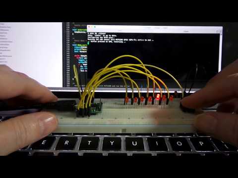
I tried this first on a breadboard


Here’s a quick demo on the breadboard:
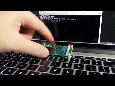
For no particular reason, I decided to put the circuit on a bit of protoboard, with pin headers to accommodate the MCP2200 DevKit. Here’s a sketch of the layout I used:

And here’s the final module
