#818 CHA-81 LED Matrix Soldering Kit
Building the CHA-81 LED Matrix Soldering Kit and investigate the principles of operation. A simple design that offers endless hours of fiddling!

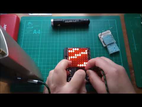
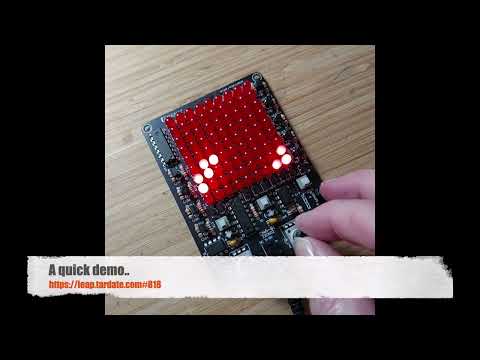
Here’s a quick demo..
Notes
I first saw this kit on Julian Ilett’s YouTube channel (see video links below) and immediately had to find one to play with!
The kit basically runs an X and Y ripple counters that drive a 9x9 LED array. Speed adjustment and directional controls make this a wonderful time-sink.
I suspect it may originally be a design from ICStation

Kit Details
I found “CHA-81 DC5-9V LED Tracking Light DIY Parts Electronic Production Kit 9X9 Dot Matrix Display” (aliexpress seller listing), purchased for SG$4.78 (Dec-2025).
Specifications as provided by the seller:
- Introduction:
CHA-81 is a LED Follow Spot Lights LED Game DIY Kit. It can make the LED move along the X-axis/Y-axis/XY-axis, and the moving direction can be controlled by the buttons. It can also adjust the speed of the LED movement, resulting in a variety of LED blinking effects.
It is a very interesting DIY electronic product which enables users to understand the circuit more clearly and learn welding skills.
Feature:
- 81pcs highlight Red LED
- Controllable movement direction for X-axis/Y-axis/XY-axis
- Controllable movement speed for X-axis/Y-axis
- Simulate LED light game tracking effect
- Perfect simple circuit
- DIY hand soldering
Parameter:
- Product Name: CHA-81 LED Follow Spot Lights LED Game DIY Kit
- Product Number: CHA-81
- Work Voltage: DC 4.5V-9.0V
- Power Type: 3.5mm Power Socket
- Color: Red LED
- Size(Installed): 97x73x24mm
Kit Parts
| No. | Component Name | PCB Marker | Parameter | Quantity |
|---|---|---|---|---|
| 1 | Metal Film Resistor | R13-R21 | 220Ω | 9 |
| 2 | Metal Film Resistor | R1 | 3.3kΩ | 1 |
| 3 | Metal Film Resistor | R2-R12 | 10kΩ | 11 |
| 4 | Potentiometer | VR1, VR2 | 100kΩ | 2 |
| 5 | Ceramic Capacitor | C6 | 0.1µF 104 | 1 |
| 6 | Monolithic Capacitor | C2,04 | 0.22µF 224 | 2 |
| 7 | Electrolytic Capacitor | C3,C5 | 1µF 50V | 2 |
| 8 | Electrolytic Capacitor | C1 | 220µF 16V | 1 |
| 9 | Red LED | L1-L81 | 5mm | 81 |
| 10 | S9014 Transistor | Q1-Q18 | TO-92 | 18 |
| 11 | Self-locking Switch | S1-S4 | 5.8*5.8mm | 4 |
| 12 | DC Socket | 3.5mm | 1 | |
| 13 | CD4017 | U2,U4 | DIP-16 | 2 |
| 14 | NE555 | U1,U3 | DIP-8 | 2 |
| 15 | USB to 3.5mm Power Wire | 80cm | 1 | |
| 16 | PCB | 97x73x1.6mm | 1 |


Circuit Design
I haven’t re-drawn the circuit, but I did verify that the following schematic from ICStation appears to be correct for the board.

How does it work? The essence:
- The two 555 timers (U1, U3) are configured as astable oscillators
- The timers provide the clock for their associated CD4017 counter
- CD4017 U2 outputs sequentially enable the LED “rows” with a high-side NPN
- NB: because the overall current is limited by the 220Ω resistor in the LED column, there is no resistor required on the NPN base
- CD4017 U4 outputs sequentially enable the LED “columns” with a low-side NPN
- At any given moment, the LED that is on ON is the one at the intersection of the enabled U2 and U4 outputs
- Pushbutton S4 changes how U4 is clocked. It switches between:
- 555 timer U3 output
- i.e. row and column speed are independently controlled
- CD4017 U2 reset
- i.e. raster mode. CD4017 U4 increments every time CD4017 U2 rolls-over
- 555 timer U3 output
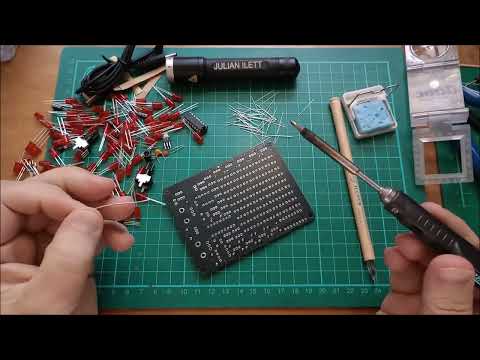
Build
Soldering was a pleasurable couple of hours.

The kit was packed with an extra S9015 and a handful of extra LEDs, but these weren’t needed as everything worked as expected.

Credits and References
- “CHA-81 DC5-9V LED Tracking Light DIY Parts Electronic Production Kit 9X9 Dot Matrix Display” (aliexpress seller listing)
- Originally purchased for SG$4.78 (Dec-2025)
- ICStation - possibly the original kit source
- Component information:
Julian Ilett’s Investigation of the Kit
Led Matrix Soldering Kit (YouTube)
What it Does - LED Matrix DIY Soldering Kit CHA-81 (YouTube)