
#120 Simple Peak Detector
The basic diode-RC peak detector.
Notes
Afrotechmods and w2aew both have some nice, clear videos on youtube explaining peak detector circuits.
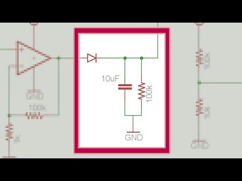
The most basic circuit uses a diode to rectify an incoming AC signal, and a capacitor to charge and hold the peak value. The RC pair holds the peak for a period governed by the RC time constant (𝛕).
Time to fully discharge is approximately 5𝛕, or in this case, about 5 seconds.
Appropriate values for the RC network depend on the signal frequency being sampled (higher frequencies will be better served by a shorter time constant).
The main problem with this circuit is the fact we lose the diode forward voltage from the output, resulting in offset measurements and an equivalent minimum input voltage sensitivity.
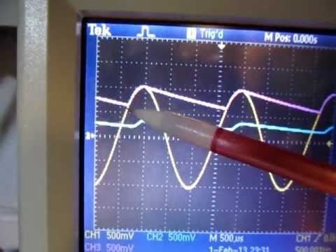
Here’s a sample trace recorded using LEAP#090 PlotNValues (a simple Processing sketch)
- upper trace is the output of the peak detector
- lower trace is the signal input (a rough triangle wave source in this test)

Construction


Credits and References
- LEAP#121 PeakDetector - OpAmp-based peak detector project
- Peak detector circuits! - Afrotechmods
- #77: Op Amp Peak Detector Tutorial, with peak detector basics - w2aew’s coverage of the basic circuit, and the improved OpAmp-based circuit