
#414 DecadeProgrammableResistor
Building an old-fashioned 7-digit decade programmable resistor with push-button control.
Notes
I found some neat pushwheel/thumbwheel decade switches, and immediately thought “decade programmable resistor”.
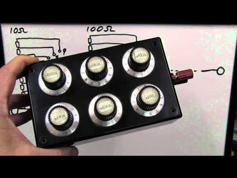
A decade box is an old-fashioned bit of test equipment, allowing an arbitrary resistance to be dialed up to order.
Dave Jones has covered the concept and shown examples. A good starting point is EEVblog #212 - DIY Decade Resistance Substitution Boxes:
Construction
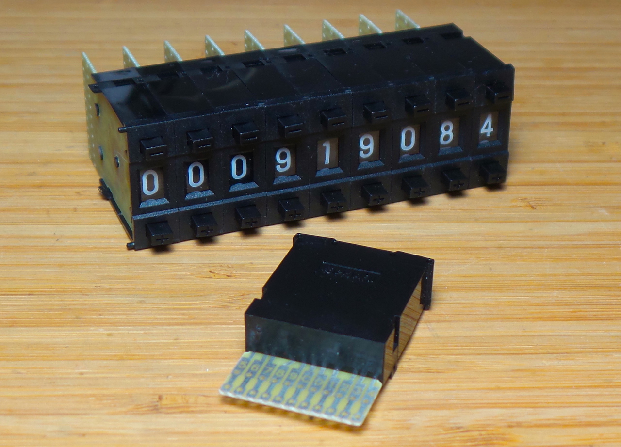
The pushwheel switches come as individual single-digit units that snap together. These are decade units with a common pole switching to one of 10 output pins. BCD versions are also available (these could be used, but require a somewhat more complicated resistor configuration to make a decade box).
Circuit Design
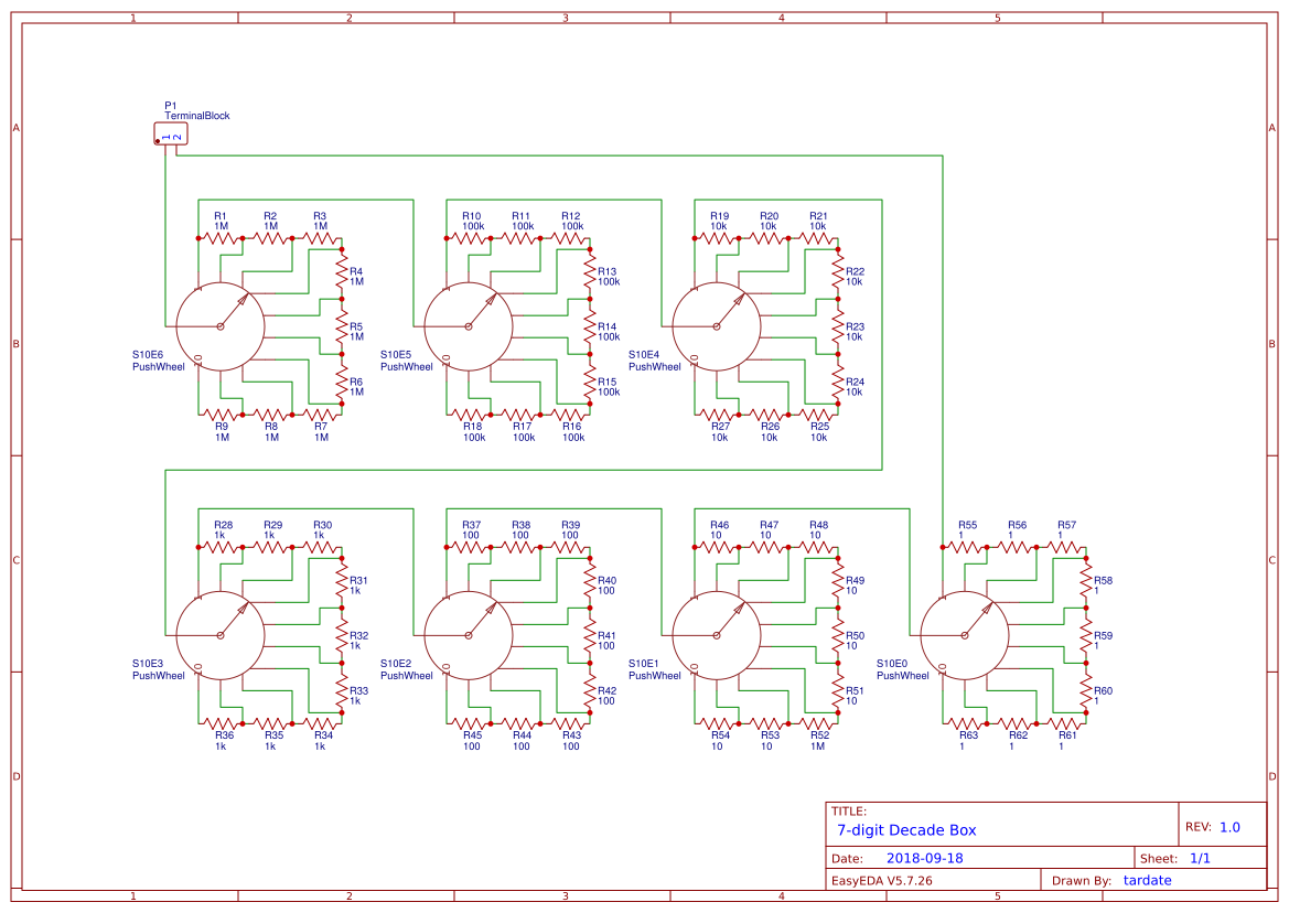
With 10-throw switches, construction is trivial:
- stage input is connected to the common
- the 10 poles are connected in a ladder with a resistor between each pole (9 resistors)
- stage output is tapped from the “0” position
- hence the resistance between input and output varies from 0 to 9x the resistor value
I’ve drawn the schematic for the 7-digit circuit here (EasyEDA)
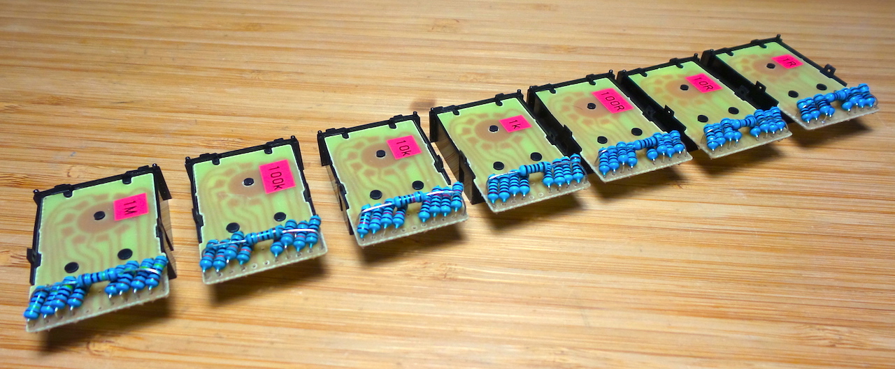
The seven units for seven digits constructed. I’ve used axial 5% resistors (1Ω, 10Ω, 100Ω, 1kΩ, 10kΩ, 100kΩ, 1MΩ respectively), and they mount quite nicely on the switches without additional wiring required.
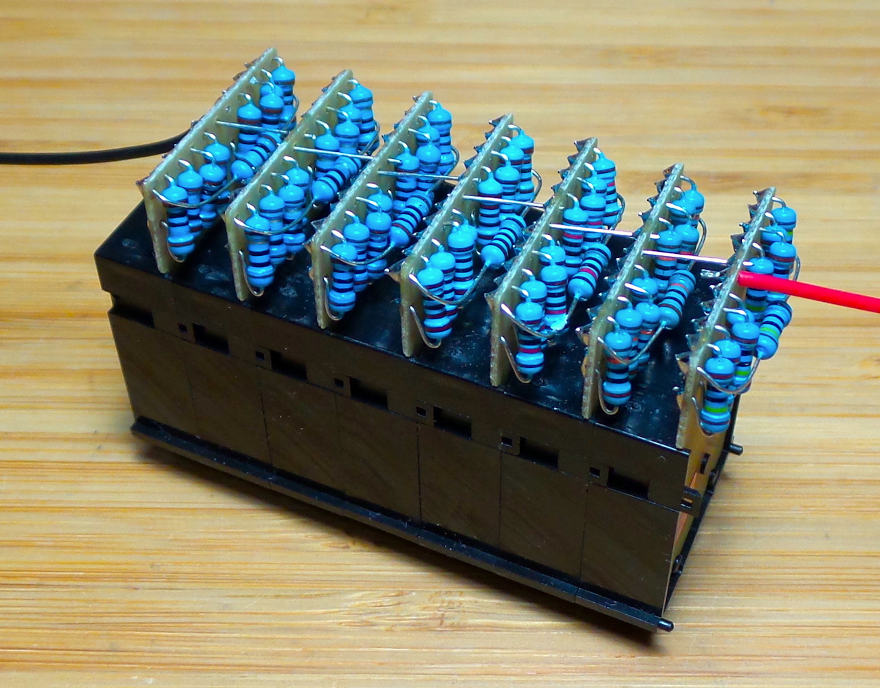
Assembled as a 7-digit bank:
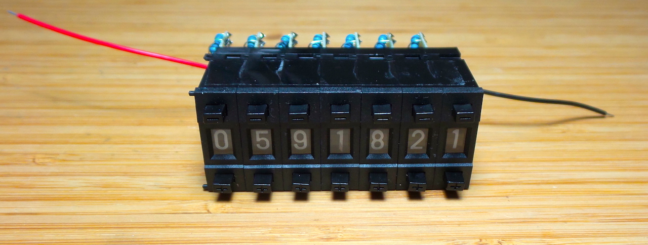
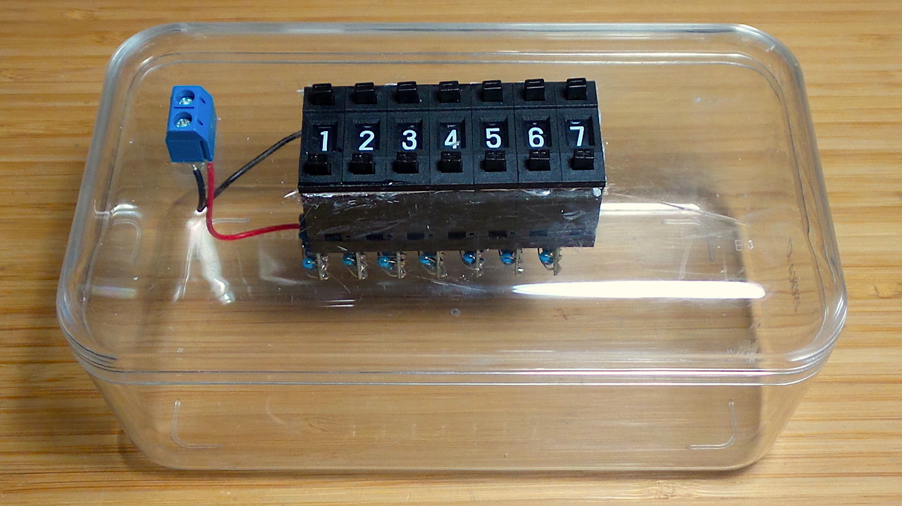
And finally encased in a transparent case (a Ferrero Rocher box iirc) with a terminal block for connectivity:
Accuracy
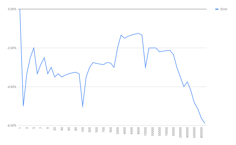
I’ve not aimed for extreme accuracy in this build - only using 5% resistors as that’s what I had on-hand. But the results are quite agreeable - generally -2% to -4% across most of the range.
I’ve tabulated a selection of readings in this Google Sheet. Measurements were taken with a cheap digital multi-meter (which may have its own accuracy challenges).
Here’s a chart of the error from 1Ω to 1MΩ:
Credits and References
- Decade box - wikipedia
- pushwheel/thumbwheel decade switches - from seller on aliexpress
- ..as mentioned on my blog