#258 ClapSwitchKit2
Practice some Boldport-style soldering on yet-another clap switch kit.
Notes
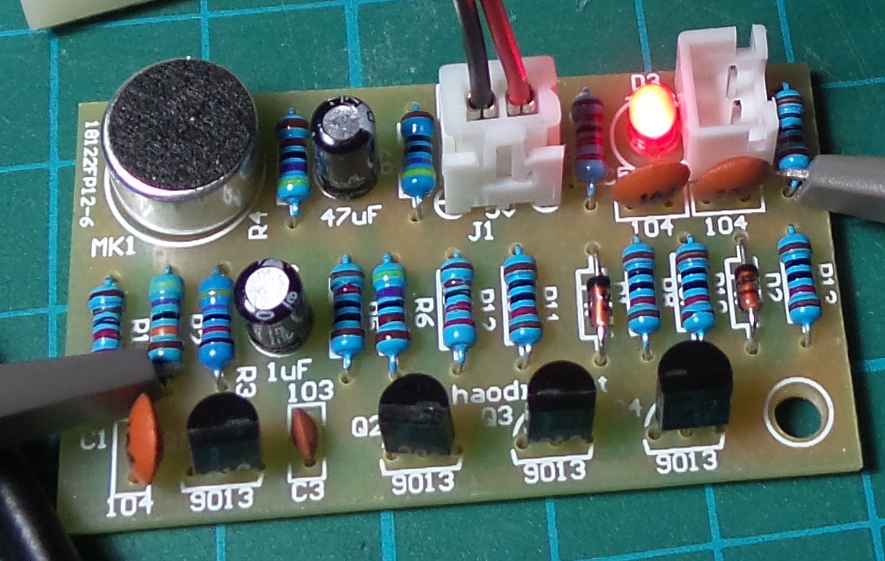
I’ve had this clap-switch (voice activated) kit sculling around for a while (another “stocking stuffer” bargain on aliexpress).
The circuit is very similar to a previous ClapSwitchKit project. The operating principle is identical, but it varies in two main ways:
- no output stage included
- component selection and values are different
So I pulled this kit out primarily to practice some Saar Drimer/Boldport-style soldering. The objective?
- beautiful solder joints
- smooth to handle
See the Making beautiful solder points video to find out more on the technique.
Comparing Solder Techniques
I used different techniques for the three solder points in the picture:

- A (left) 2-pass boldport style: solder; clip down to the board; re-flow and make the dome
- B (middle) the cheats’ boldport 1-pass style: blu-tack the part and clip the lead first, then solder with dome on the first pass
- C (right) normal technique - lead clipped after soldering
- Note the joint in the upper right - now that’s more like it! … though still not very shiny
A and B are clearly superior to C - which is asymmetrical and not finger-safe.
In practice, I can’t tell much difference between the results of A and B. I think for now my preferred style is B:
- place the parts - I use blu-tack to hold them in place if necessary
- clip the leads as close to trim with the board as possible
- solder and make the dome in one pass
- side benefit is you get to harvest the clipped leads free of solder and flux (if you care - I keep some around for ad-hoc protoboard wiring)
Making the “Dome”
At first, I had real trouble making smooth symmetrical domes. I’d always end up with “meringue tips” when I drew the iron away. The technique that seems to work best for me is:
- make sure the iron isn’t overloaded with solder
- withdraw the iron by first pulling down and around the nearside of the solder joint, nudge in a little then withdraw smoothly
This sounds more like icing a cake!
Making Shiny Joints
So now I’m getting decent domes (most of the time) that are electrically and mechanically sound. But they are rarely shiny.
“Shiny” is not usaully a QA issue for solder points (advice abounds on how it is not important). This is not to be confused with dry joints, that will be both dull and flakey/crystaline.
Google delivers many opinions, for example:
- Why aren’t my solder connnections shiny and perfect?
- lead free soldering - Why are some joints shiny?
The main advice for why solder points are not shiny seems to boil down to one or more of the following:
- unleaded solder “rarely produces shiny solder joints”
- no Silver (Ag) in the solder - especially lead free
- iron is too hot
- iron is too cold (but may be confused with dry joint issues)
- cooling too fast/airconditioning/cold-board
- contamination
- not enough flux
- disturbed before cooled
In other words, lots of theories!
So I ran some tests:
- I’m using WL-0510 B-1 0.5mm 63Sn/37Pb
- I tested with a range of iron temperatures from 250˚C to 325˚C
- with A/C (24˚C) and without (probably heading to 27˚C)
- with and without additional flux
… and I get pretty much the same result all the time: a nice shiny ball when I remove the iron, then as it cools, it gets to a point when the ball instantly frosts over and I end up with a “dull” solder point.
It seems pretty clear that it is oxidizing at the phase-change from liquid to solid. Not sure what to try next to control this…
… except elbow grease;-) Turns out that with a bit of polish (using solder-station copper wool), I get some of the shine back.
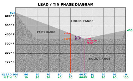
So after a bit more research, I am suspecting the dullness created during the phase change from liquid to solid is due to the eutectic property of 63Sn/37Pb. As you can see in the phase diagram below, 63/37 is the alloy with almost perfect eutectic properties (meaning it goes straight from liquid to solid without passing an intermediate plastic phase).
REALLY Shiny Domes
Since everything I tried so far hadn’t made much difference (temperature, technique, aircon), the only thing left to try is different solder.
So I got hold of some Pro’sKit 9S002 Solder (62% Sn, 37% Pb, 2% Ag) … and the difference is amazing:
- it creates “domes” with hardly any effort
- and they are all nice and shiny
Here’s a side-by-side comparison using the same iron and tip, and both at 275˚C.
- on the left: 62Sn/37Pb/2Ag. Soldering is a breeze, and the results are perfectly formed and shiny
- on the right: 63Sn/37Pb. Making domes is “hard work” and they rarely turn out shiny
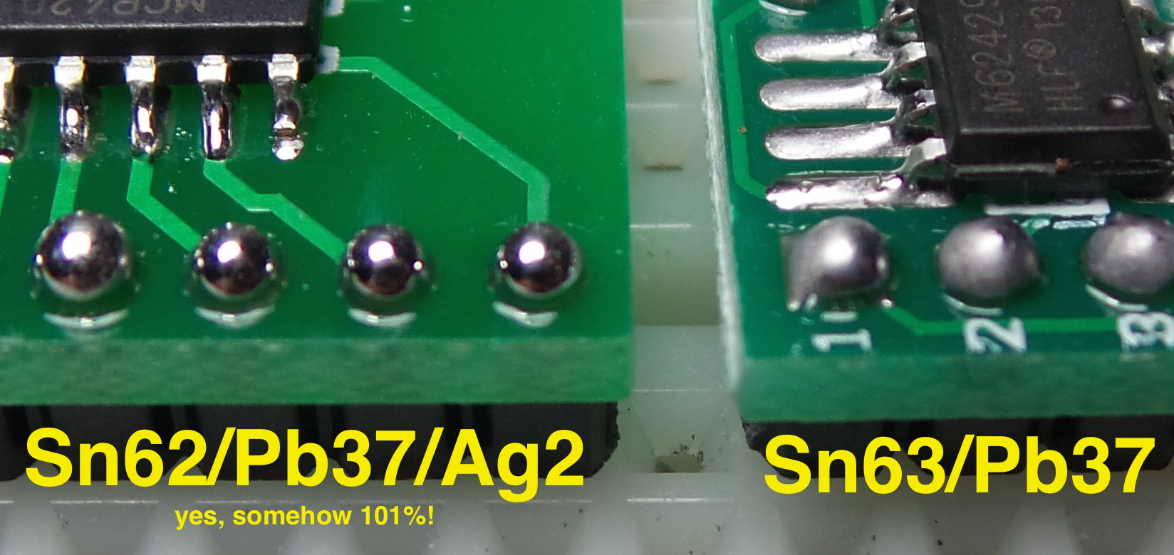
I’ll need to do some more tests to determine if the problems I was originally seeing are typical of a 63Sn/37Pb formulation, or if perhaps I just have some very poorly manufactured 63Sn/37Pb.
First Pass on the Board
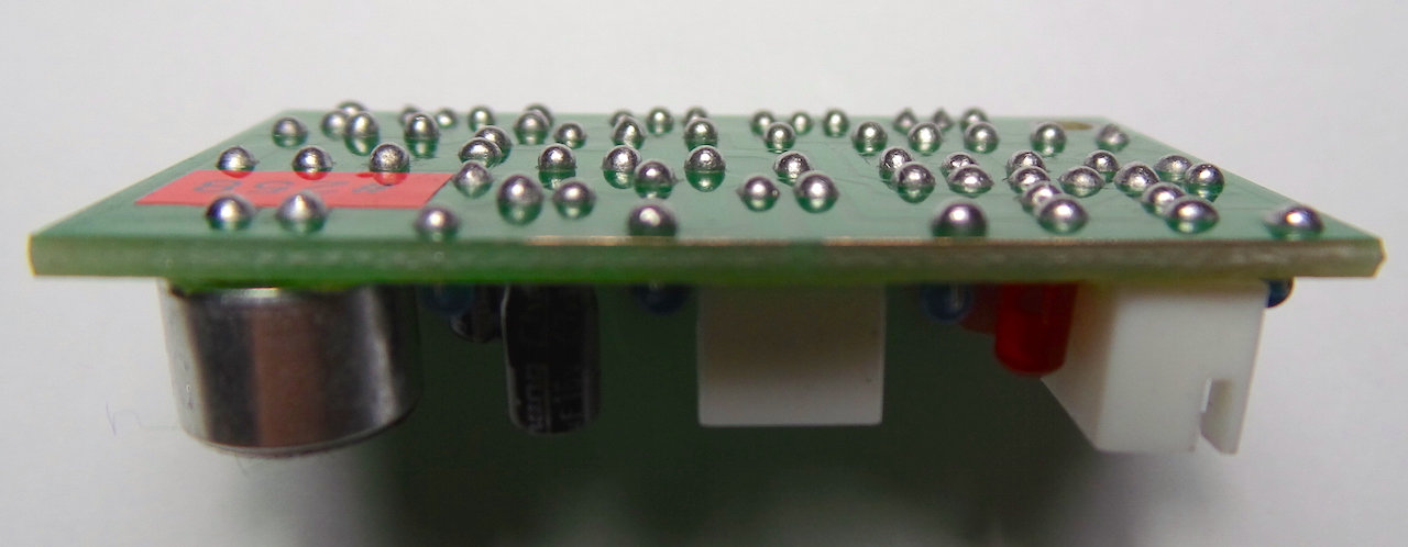
Here is the first pass. Electrically/mechanically sound but not really perfect “Boldport” quality:
- my dome sizes/shapes are a bit uneven
- a few meringue tips
- dull (see above) but brightened up with a bit of buffing
Circuit Performance
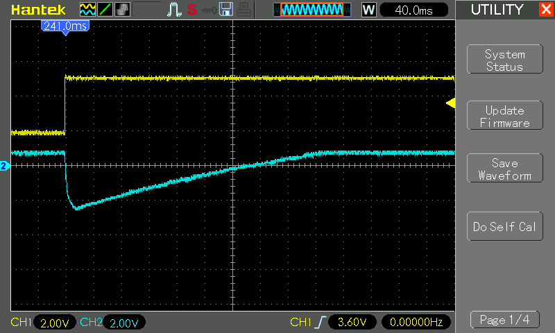
This is a trace of the “clap-on” transition
- CH1 (yellow) is the output signal
- CH2 (blue) is the piezo speaker input to the base of Q1
- no vertical offset
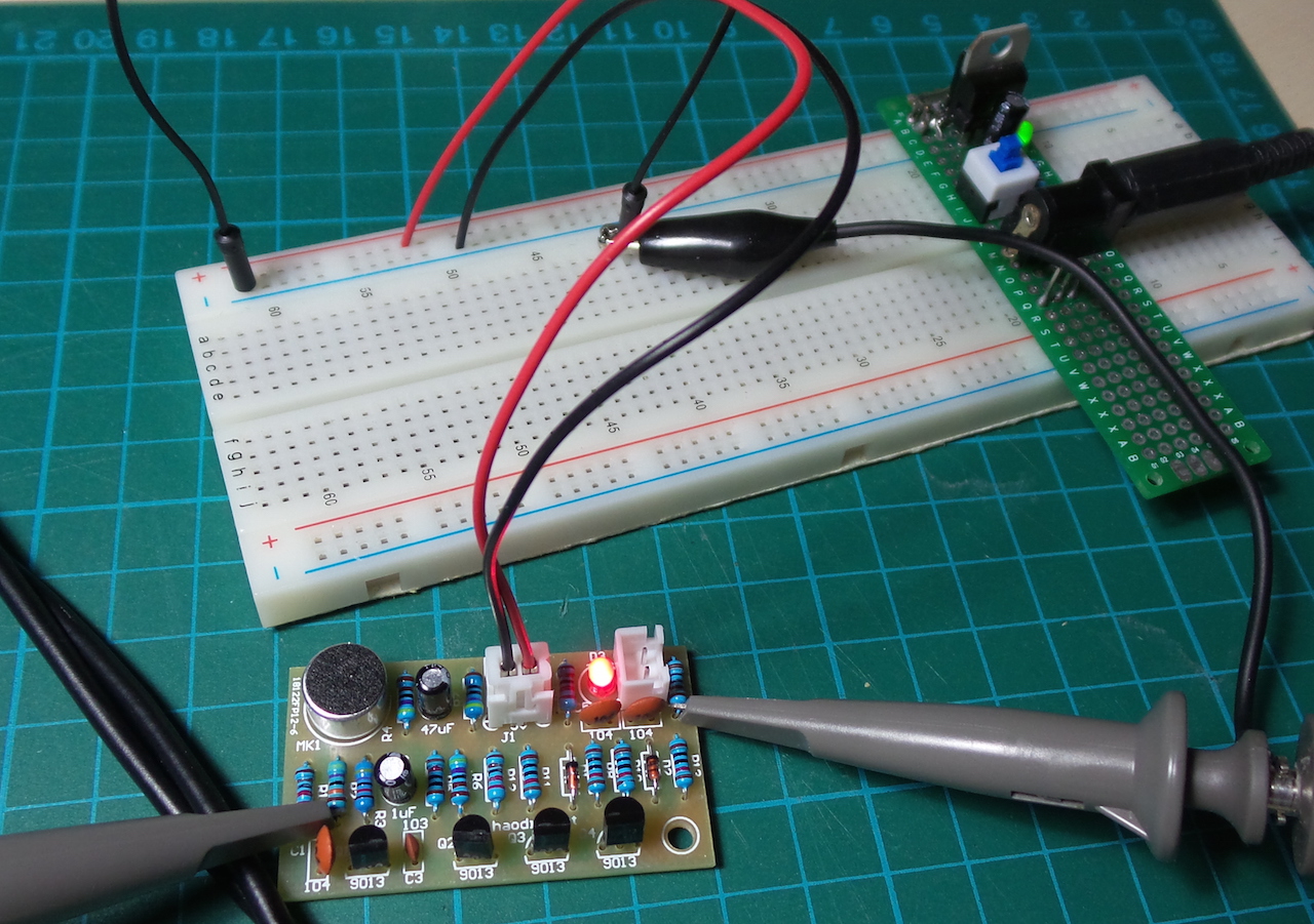
The board under test…
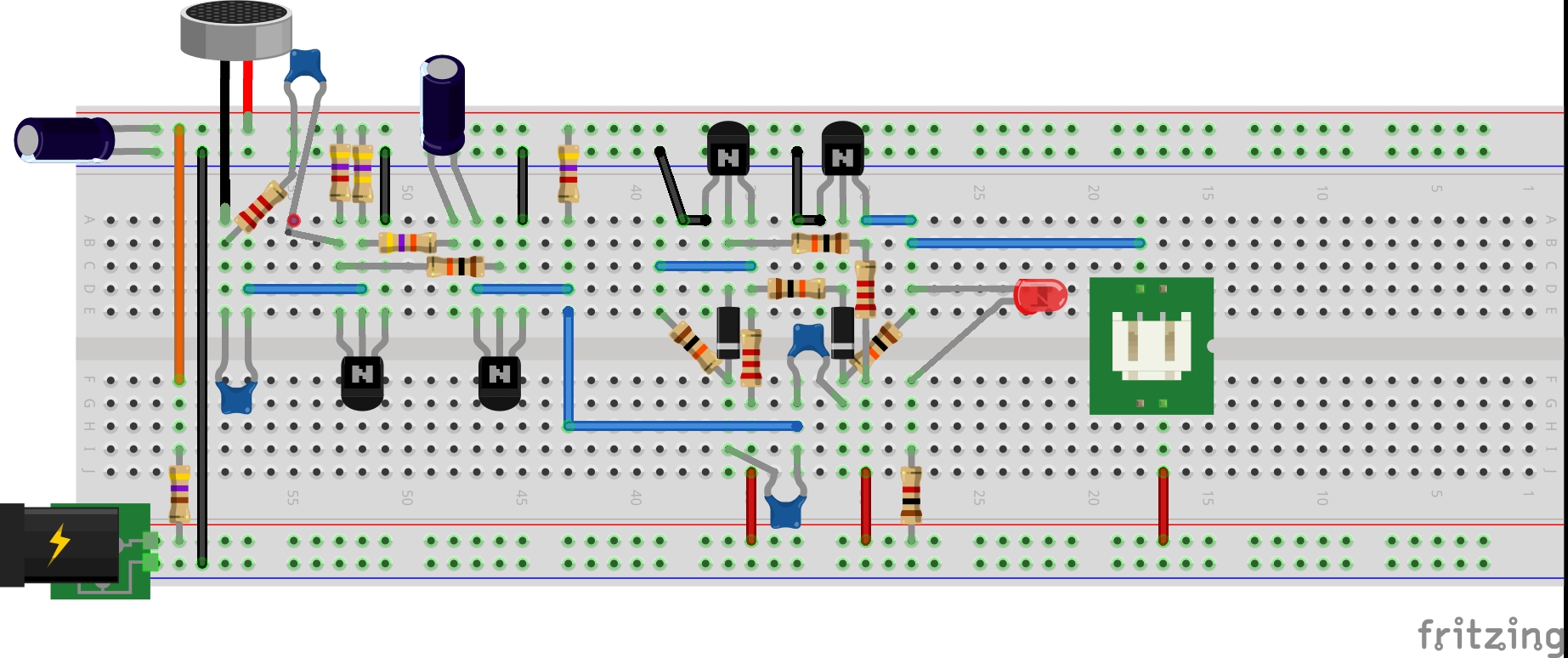
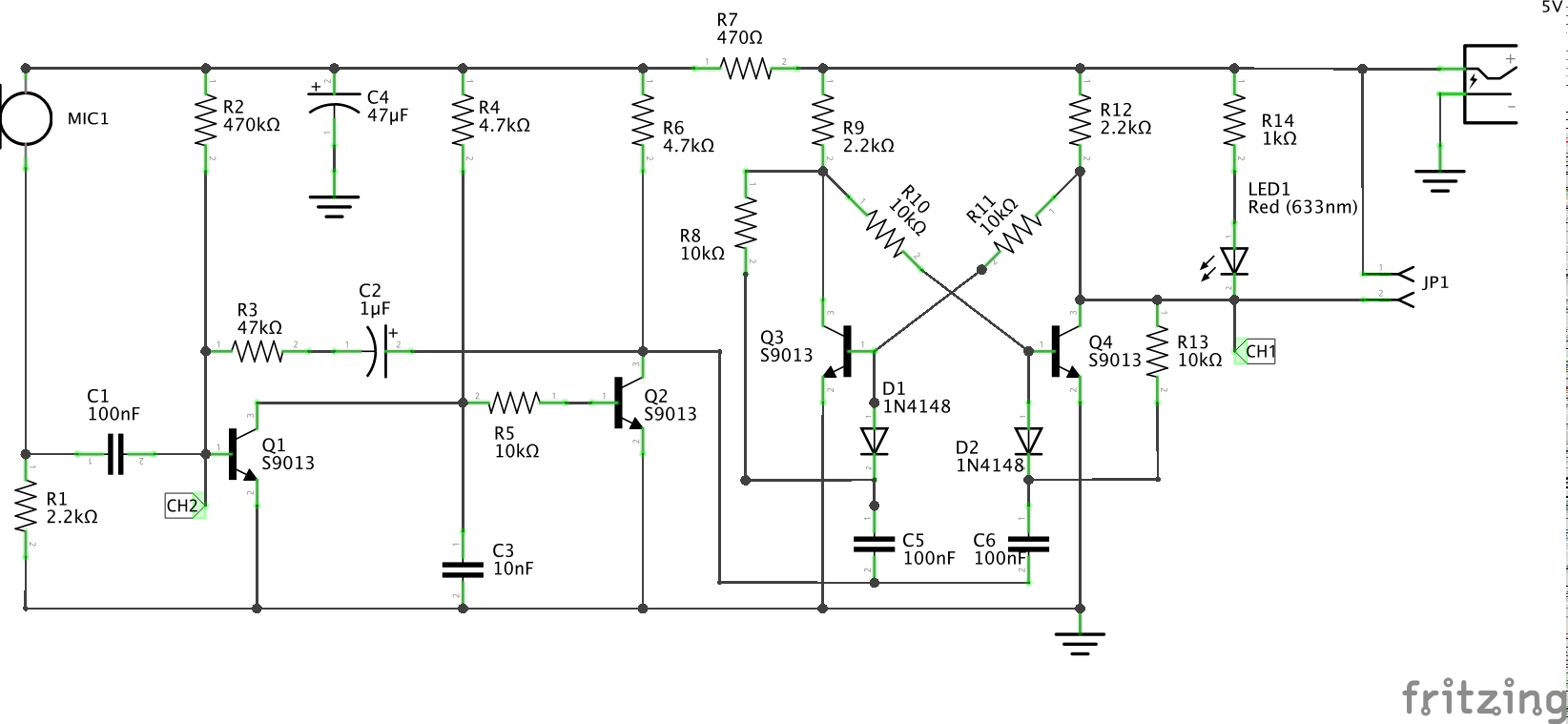
Construction

Credits and References
- The clap switch - from a seller on aliexpress
- LEAP: ClapSwitchKit - another clap-switch kit project
- Making beautiful solder points - the boldport way
- Common Causes of Soldering Tip Failure - includes some great info on the metallurgy of solder
- Soldering for Show - great article
- 7.1.1 Soldering Basics - Circuit Technology Center
- WL-0510 B-1 0.5mm 63Sn/37Pb
- Pro’sKit 9S002 Solder Wire W/2% AG 17G
- ..as mentioned on my blog

