#561 Aguhajsu 1S/3A BMS
Reviewing and testing the Aguhajsu 1S 3A battery protection module for a single 18650 lithium-ion cell.
Notes
Aguhajsu 1S 3A BMS is a tiny PCB. The smarts are provided by two ICs:
The DW01 provides four basic protection functions:
- over-charge
- over-discharge
- over-current
- short-circuit
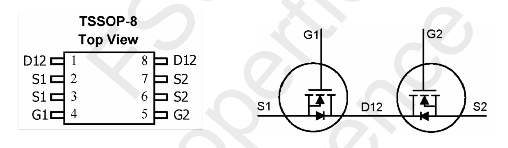
The FS8205A provides the power MOSFETs that are controlled by the DW01 to cut/enable power as required.
The module provides protection only. It does not manage the charging profile (i.e. constant current control) - this must be handled separately.
The form factor of the module (a long thin strip) perhaps makes this module most suitable for adding protection to “pillow pack” lithium batteries.
Andreas Spiess has a good video explaining how similar battery protection circuits work:
Module Specifications
Product blurb from the seller/manufacturer:
The main IC uses the original Fujing imported components. With overcharge, over discharge, over current, short circuit and other protection functions, for a variety of shapes of various shapes 3.7V lithium battery. It adopts rich crystal protection IC, high quality MOSFET such as VISHAY, AOS and IR, FR-4 low temperature coefficient plate, excellent design, fine workmanship and comprehensive test. It is small in size and suitable for many applications requiring high integration and low cost. It can meet various performance requirements and ensure the absolute safety and reliability of the battery pack.
Technical Parameters:
- Overcharge detection voltage: 4.25 ± 0.05V
- Overcharge release voltage: 4.23 ± 0.05V
- Overdischarge detection voltage: 2.54 ± 0.1V
- Overcurrent detection current: 1-3A
Wiring instructions:
- B+ is connected to the positive battery.
- B- connect the battery negative.
- P+ is the power input/output positive
- P- is the power input/output negative
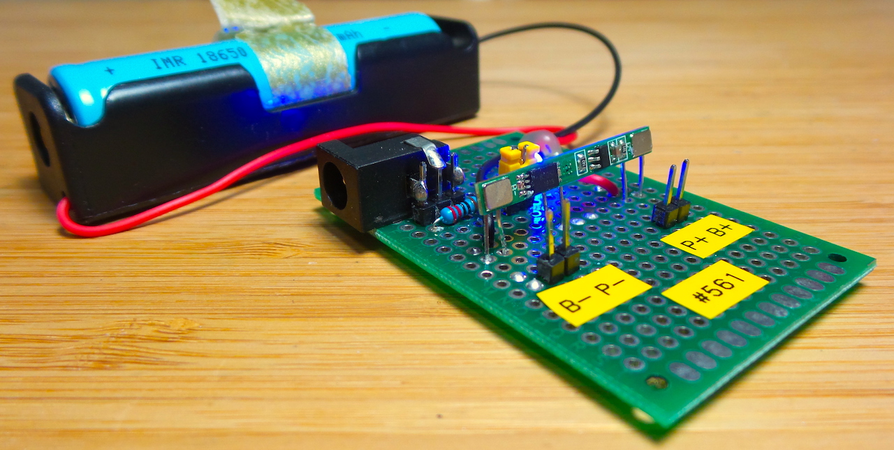
Construction
I’ve drawn the schematic for the module circuit here (EasyEDA). The circuit used in the module is literally exactly as depicted in the DW01 datasheet.
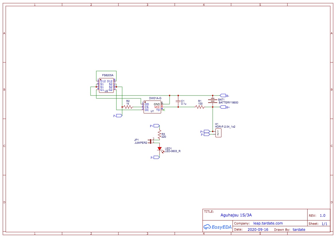
For testing purposes, I’ve included an additional indicator LED that can be disabled with a jumper, and mounted the module on some protoboard with connectors for power and some test points.
About the DW01
| Pin | Symbol | Description |
|---|---|---|
| 1 | OD | MOSFET gate connection pin for discharge control |
| 2 | CS | Input pin for current sense, charger detect |
| 3 | OC | MOSFET gate connection pin for charge control |
| 4 | TD | Test pin for reduce delay time |
| 5 | VCC/VDD | Power supply, through a resistor (R1) |
| 6 | GND/VSS | Ground pin |

About the FS8205A
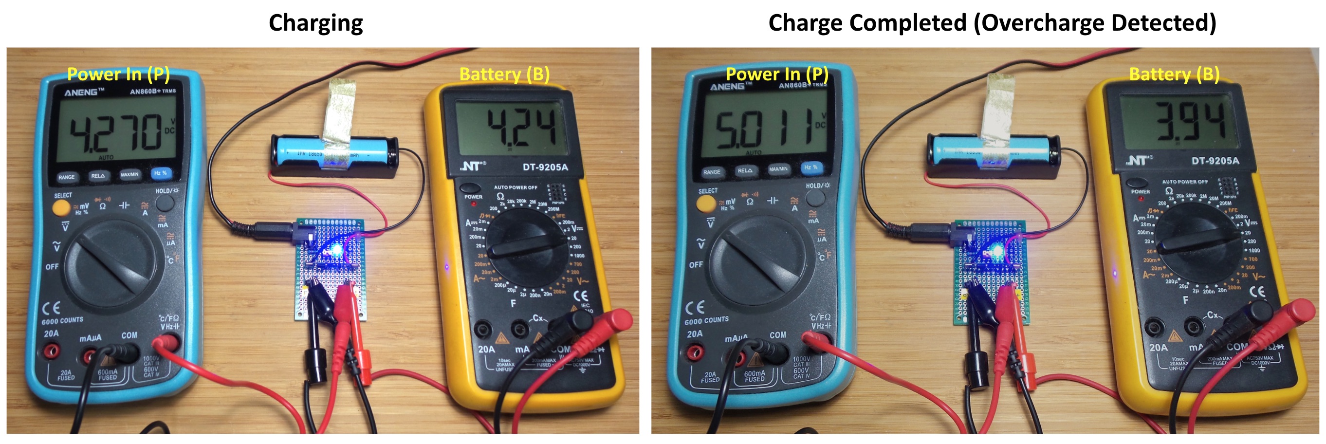
Testing a Charge
I’m testing a charge cycle with an old 1300mAh battery. A good rule of thumb is to charge at a maximum current of around 0.5C (650mA), so I set my bench power supply for 5V with 500mA current limit for this charge test. This is a very crude constant current charge profile.
The over-charge protection kicks in as expected at around 4.3V: