#860 555 Upside Down
Testing an interesting upside down astable 555 configuration that achieves +duty cycle control all the way down to 0% without an additional inverter stage.
Notes
The “555 upside down” is a variation of the typical 555 astable configuration that was presented in Elektor 8/2026, page 50.
It positions the charging capacitor on the high side of the 555 comparators, allowing duty cycles down to 0%. The typical minimum duty cycle in the standard astable configuration is about 50% - see LEAP#016 555 Timer - A-Stable Oscillator.
This is an interesting technique for achieving low +duty cycle control, without the need for an additional inverter stage after the timer.
Circuit Design
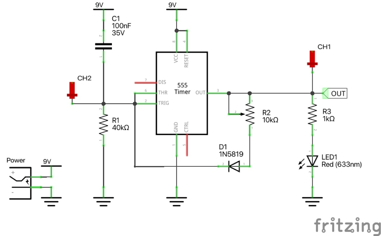
Designed with Fritzing: see UpsideDown.fzz.
I ended up varying the published schematic for a number of reasons:
- I substituted a 1N5819 for the BAT85 as I don’t have any on-hand. The 1N5819 should have a forward voltage performance almost as low as the BAT85
- Experimentally, I determined R1 should be around 4*R2 to allow the pot to be effective over most of its range. With the original R1=10kΩ and R2=5kΩ, the duty cycle control only covered about 20% of the pot’s range.
- C1 and R1 can be adjusted depending on the application:
- lower capacitance (such as 100nF I ended up using) is good for frequencies above visibly detected blinking e,g, for LED dimming
- higher capacitance can put the output into the visibly detectable e.g. for LED blinking
| Item | Original | Revised |
|---|---|---|
| D1 | BAT85 | 1N5819 |
| C1 | 1µF | 100nF |
| R1 | 10kΩ | 40kΩ |
| R2 | 5kΩ pot | 10kΩ pot |
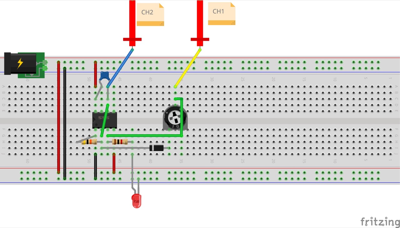
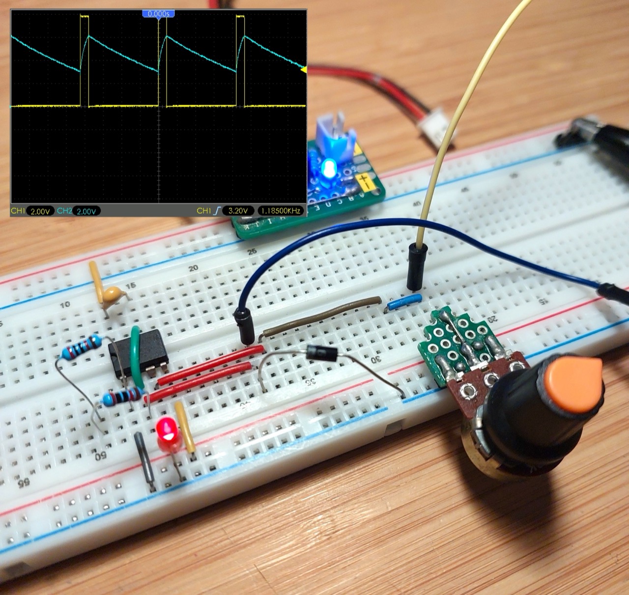
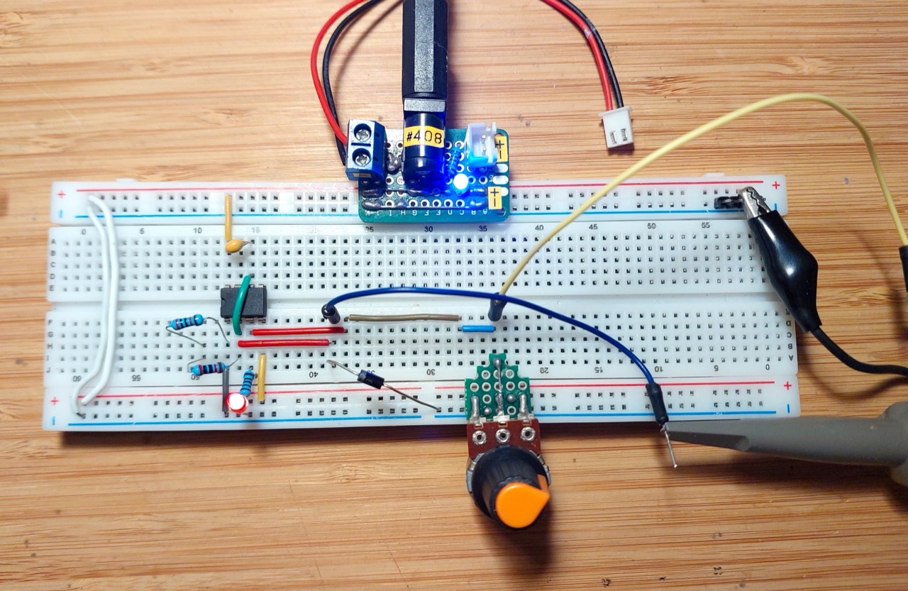
Setup on a breadboard for testing:
Test Results
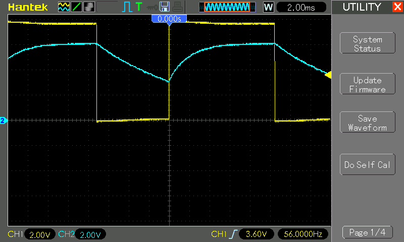
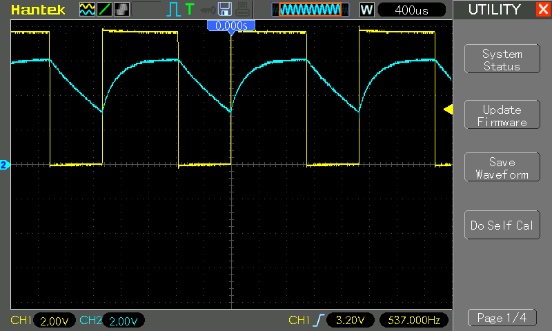
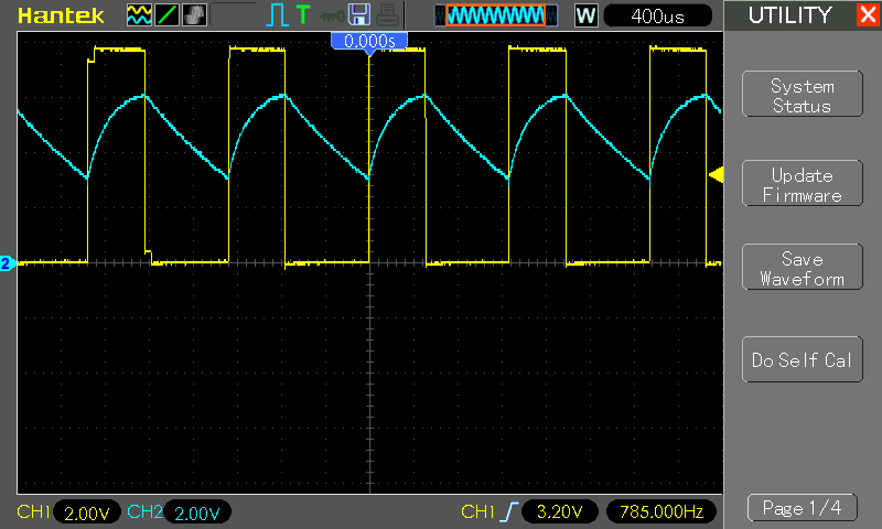
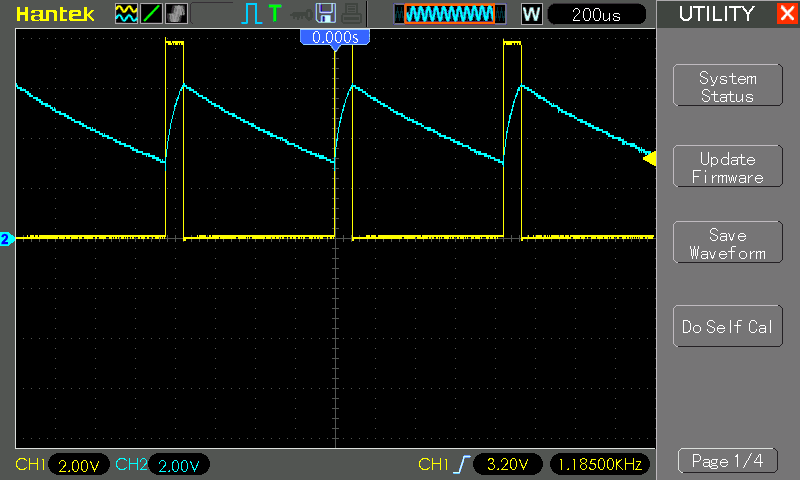
In the following tests, the scope connections are as follows:
| Channel | Colour | Connection |
|---|---|---|
| CH1 | Yellow | timer output (pin 3) |
| CH2 | Blue | threshold/trigger (pin 2 & 6) |
Original Timing Components
Components:
- D1=1N5819
- VCC=9V
- C1=1µF
- R1=10kΩ
- R2=5kΩ pot
Note:
- operates quite well at 9V
- reducing the supply voltage e.g. 5V reduces the maximum +duty cycle possible
Adjusted for 56 Hz at 60% +duty:
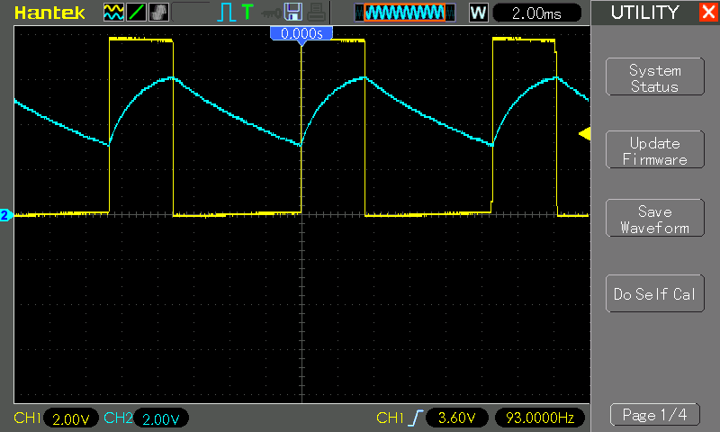
Adjusted for 93 Hz at 33% +duty:
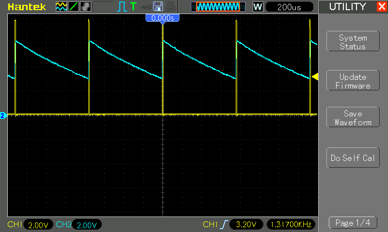
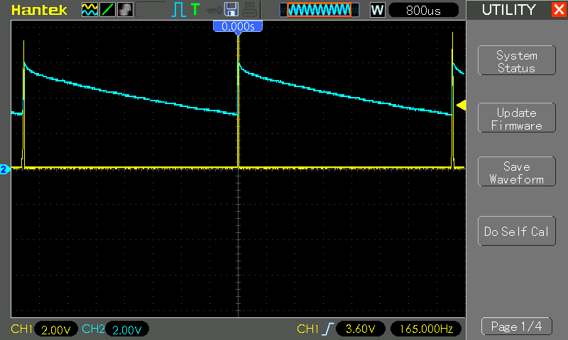
Adjusted for 165 Hz at 1% +duty:
Final Timing Components
Components:
- D1=1N5819
- VCC=9V
- C1=100nF
- R1=40kΩ (actually 2x20kΩ in series)
- R2=10kΩ pot
Adjusted for 537 Hz at 60% +duty:
Adjusted for 785 Hz at 40% +duty:
Adjusted for 1185 Hz at 10% +duty:
Adjusted for 1317 Hz at 1% +duty: