
#785 Tick Tock
A 555/74LS73 circuit that generates a tick-tock sound sequence at distinct frequencies.

Here’s a quick demo..
Notes
I wanted to create a mechanical clock-like “tick-tock” sound generator. I’ve found some inspiration in existing circuits:
- Tic-Tic Sound Generator using IC 555
- Tick Tock Sound Generator Circuit using 555 Timer IC
- Clock with LED Pendulum and Tick Tock Sound
However they all seem to cheat and generate the tick/tock pulses at the same frequency. Some circuits don’t actually set a frequency, and just rely on a single click of the speaker. I want something better, where the audio frequencies are specific and distinct for tick and tock.
The circuit I’ve come up with here is quite a naïve composition of the elements needed to build up a tunable tick-tock sound:
- adjustable clock frequency (precalculated for 1 Hz)
- specific “tick” and “tock” frequencies
- can be altered by changing R5,R6,C4 values
- could be made user-adjustable by replacing R5 and R6 with pots
There is probably a much more elegant and straight-forward way to achieve this, but I haven’t a suitable circuit yet. Something to ponder..
Circuit Design
Designed with Fritzing: see TickTock.fzz.
- U1: 555 configured as a low-frequency oscillator to provide the time signal:
- 1Hz @ 50.7% duty cycle
- with R1 = 2kΩ, R2 = 71kΩ (100kΩ pot), C1 = 10µF
- U2: 555 monostable edge-triggered by U1, converts the time sync to short pulses of defined duration (
TICK):- 52ms high
- with R3 = 4.7kΩ, C3 = 10µF
- U3: 555 audio oscillator
- U4: 74LS73 latch
- clocked by U2 pulses (
TICK) - alternating high/low Q1 output (
FNOTCH)
- clocked by U2 pulses (


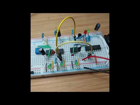
For the breadboard build, I have added LED+Resistor indicators to the main signals: CLOCK, TICK FNOTCH (Q1 and ~Q1), AF.
These are not shown in the schematic.

The distinct tick/tock signals are capture on the scope below, where:
- CH1 (Yellow) -
AFoutput from U3 - CH2 (Blue) -
TICKoutput from U2 - CH3 (Red) -
CLOCKoutput from U1


Credits and References
- LM555 Datasheet
- 74LS73 datasheet - Dual JK Flip-Flop with Clear
- Visual 555 Calculator