
#045 Simple Siren
Classic timer circuit producing a two-tone oscillation through control voltage adjustment of the second timer.

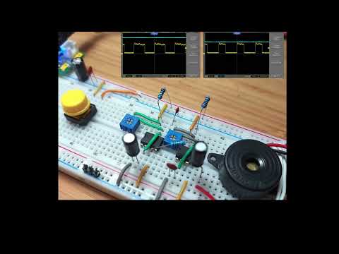
Here’s a quick demo..
Notes
This circuit uses two 555 timers to create a two-tone siren, sometimes characterised as a “ding dong”. One can find variations of this circuit in many places, for example:
- Ding Dong Sound Generator Circuit published by ElectronicsHub.
- Police Siren on Talking Electronics
- Police Siren circuit on 555 Timer Circuits.
It operates with two oscillating 555 timers chained together:
- the first 555 provides the low frequency oscillation between high and low output states. The frequency is determined by the values of R1, VR1 and C1.
- The pin 3 output of the first timer switches the control voltage of the second 555 timer, adjusting its frequency.
- The oscillation of the second 555 drives the output piezo, and the frequency is modified by the control voltage.
Construction
Designed with Fritzing: see SimpleSiren.fzz.


Testing
The first 555 provides the low frequency oscillation between high and low output states. The frequency is determined by the values of R1, VR1 and C1. With R1=2kΩ, VR1 at 10kΩ and C1=47μF this runs at 1.4Hz and 55% duty cycle.
The pin 3 output of the first timer switches the control voltage of the second 555 timer.
In practice, with R3=1kΩ in place, the control voltage (Vcontrol) is was measured as follows:
- high
Vcontrol: 4.80V - low
Vcontrol: 6.64V VCC: 9.2V
When Vcontrol = 4.80V, the frequency of the oscillation is 287 Hz - see the actual calculation on WolframAlpha
When Vcontrol = 6.64V, the frequency of the oscillation reduces to 211 Hz - see the actual calculation on WolframAlpha.
The derivation of the formula considering a control voltage is explained in a question on EE.SE. The formula with variables as named in this circuit is:
f = 1/( C2.(R2+VR2)ln(1 + Vcontrol/(2(Vcc - Vcontrol))) + C2.VR2.ln(2) )
In practice, I’m seeing the frequency alternate between around 241 Hz and 275 Hz, as measured on an oscilloscope:
- CH1 (Yellow): second timer output (pin 3)
- CH2 (Blue): second timer control voltage (pin 5)


Credits and References
- LM555 Datasheet
- Visual 555 Calculator
- What is the equation for the 555 timer control voltage? - Q&A on EE.SE
- Reference Circuits:
- Ding Dong Sound Generator Circuit published by ElectronicsHub.
- Police Siren on Talking Electronics
- Police Siren circuit on 555 Timer Circuits.