#277 Touchy
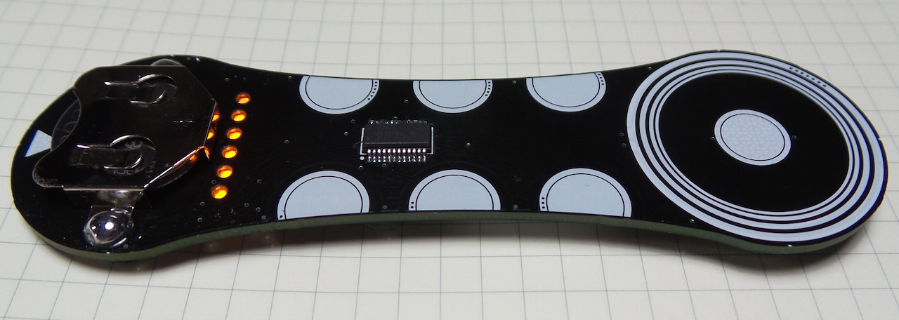
Touchy is a capacitive touch input device with on-board Sleepy Bee microcontroller (Boldport Club Project #7).
Notes
I gather this project was designed for BolportClub by Saar Drimer as usual, but with coding and examples provided by #DefineElectronics.
No disappointments here - another beautiful board to add to my growing collection of club projects! We’ve seen touch input in club projects before (The Tap), but there are two other features of this project that provide a special jolt of novelty for me:
- first time I’ve worked with a Silicon Labs’ Sleepy Bee microcontroller
- all surface mount construction - including the QSOP24 microcontroller package that has an insane 0.625mm pin pitch!
When completed, the board features:
- six capacitive-touch ‘buttons’ and one scroll-wheel.
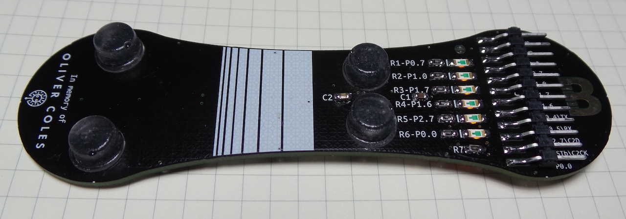
- pin header for external power, programming, and direct access to the LED control lines
- on-board coin cell 3V battery (CR2032).
Parts
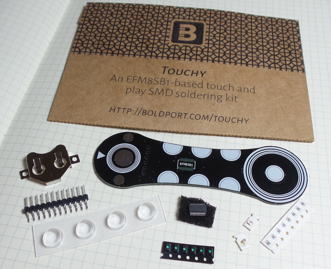
| Ref | Item | Qty |
|---|---|---|
| U1 | 8 Bit Microcontroller, Sleepy Bee, EFM8SB1, Silicon Labs EFM8SB10F8G-A-QSOP24 | 1 |
| LED1-6 | 1206 Reverse mount orange LED, Kingbright KPTL-3216SECK | 6 |
| J1 | 12 contact 2.54 mm SMD header, Samtec TSM-112-01-T-SH | 1 |
| R1-7 | 0805 1KΩ resistors, Multicomp MCWR08X1001FTL | 8 |
| C2 | 0805 0.1μF ceramic capacitor, Multicomp MC0805B104K500CT | 1 |
| C1 | 0805 1μF ceramic capacitor, Multicomp MC0805F105Z160CT | 1 |
| - | CR2032 coin-cell battery holder, Multicomp BC-2001 | 1 |
| - | Stick-on bumper, Multicomp 2565 | 4 |
Construction
Soldering the EFM8SB10F8G-A-QSOP24 microcontroller
The microcontroller comes in a QSOP24 package that has a 0.625mm pin pitch. This is eye-strainingly small, and I knew would be the biggest challenge so I did it first. I also did it first because I planned to use hot-air gun, and I didn’t want already-installed components falling off the backside of the board!
Ideally I’d use solder paste for this but don’t have any available right now, so the technique I used was this:
- load more solder on the pads with an iron
- for this I’m using leaded 63sn/37pb with 1.2% flux. It is not the solder I use for “shiny domes” but I find it better for fine work, and since it is eutectic it is ideal for fixing small parts in place without them shifting as the solder cools.
- prep the pads for reflow with flux (kester #951 flux pen)
- place the QSOP24 on the pads
- reflow with a hot-air-gun
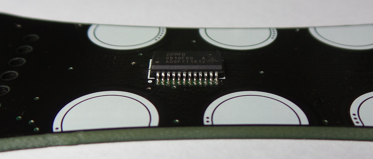
After that, I did continuity and bridging test for each pin with a multimeter. I found three pins that hadn’t connected to the pads properly. To fix these:
- touch up with an iron with a needle-point tip
- quick reflow with a hot-air-gun to “prettify” the joint
- restest
The result is visually pretty pleasing, and also electrically sound:
Adding the Battery Clip
I added the battery clip next so I could finish work on one side of the board before completing the surface mount components on the other side.
For this I switched to 2% Ag (63sn37pb2Ag) that I find best for shiny domes … and made big shiny balls!
Note that I clipped the corners of the battery mount so they wouldn’t protrude beyond the edge of the solder pads.

Completed top-side of the board:
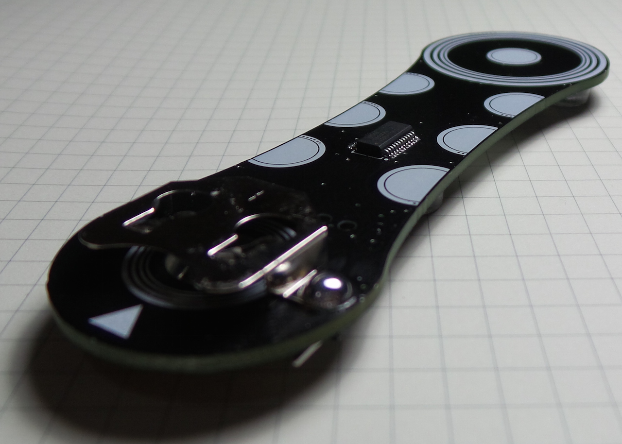
Reverse Side Components
The 0805 compoinents are SO BIG after doing the QSOP24. These components all went down without trouble. I used my “shiny dome” solder, 2% Ag (63sn37pb2Ag).
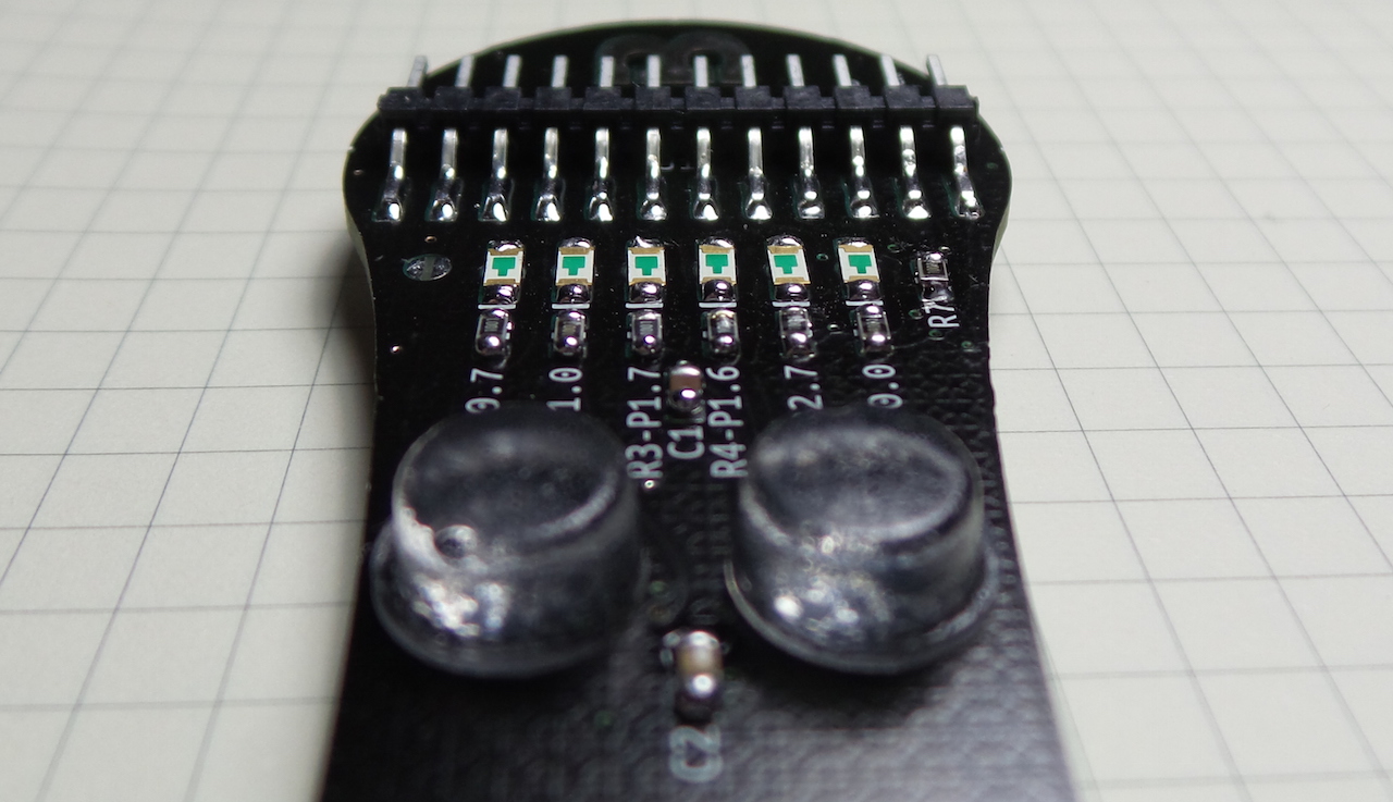
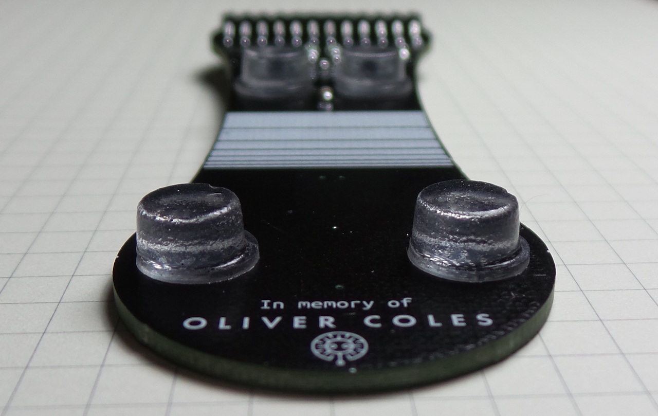
The only trouble I had was deciding where to stick the feet.. and now I notice the base of the feet are not symmetrical - I should have rotated that one of the left by 180˚. Am I getting too obsessive???
Programming
This tutorial by #DefineElectronics is a great start:
The Silicon Labs’ Simplicty Studio is used to edit and compile programs for the microcontroller. I haven’t tried this yet, but things look promising as there is a Windows, Mac and Linux installer. It seems very heavy-weight though (another Eclipse-based IDE).
Thankfully we don’t need that to get the board up and running, as there are pre-compiled samples available.
Restart in bootloader mode
The bootloader is pre-installed, so on first power-up the board is ready and waiting for programming commands (there is no pre-installed program).
After the microcontroller has been programmed, it can be put back into bootloader mode like this:
- Remove battery
- Disconnect programmer (or just RX)
- Pull RSTb to ground
- Reconnect the battery
- Remove RSTb pull-to-ground
- Connect programmer & program
Programming (MacOSX)
To test the board I uploaded the pre-compiled “Simple” program. Bottom line: It all worked fine!
The BC_Touchy_Firmware repository not only contains the Simple program (source and pre-compiled images) but also programming tools.
Since I’m running on MacOSX, I used the efm8load.py script to send the program to the microcontroller. The script is an interesting read - very simple, just dumps the file out the port and checks the acknowledgements coming back!
I’m using a cheap CH340G-based USB to UART adapter with
suitable drivers installed.
This adapter can be switched between 3.3V and 5V - I used it switched to 3.3V here.
For the particular USB port I used in the examples below, it showed up in my system as /dev/cu.wchusbserial14520
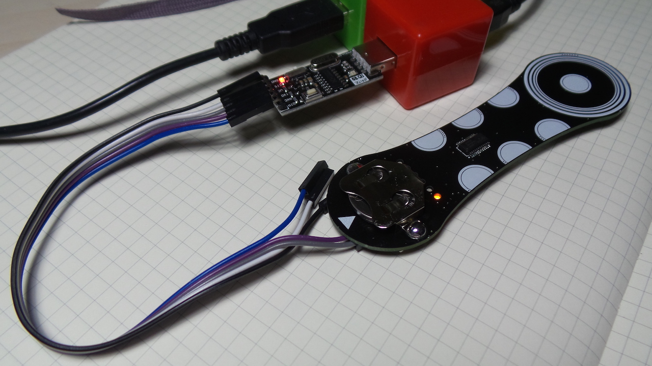
Here’s the process I used to upload the program. At the start, the device is already in bootloader mode.
Clone the repo:
git clone git@github.com:HashDefineElectronics/BC_Touchy_Firmware.git
Send the Simple.efm8 program to the microcontroller over the correct port:
$ python BC_Touchy_Firmware/Bootloader/Tools/Source/efm8load.py -p /dev/cu.wchusbserial14520 -t BC_Touchy_Firmware/HEX/Simple.efm8
Download over port: /dev/cu.wchusbserial14520

$ 04 31 A5 F1 00 -> @
$ 83 32 00 00 FF 0B 98 8C -> @
$ 83 33 00 80 28 CE 8D F0 -> @
$ 83 33 01 00 50 06 87 F0 -> @
$ 83 33 01 80 8A 83 74 01 -> @
$ 83 32 02 00 E9 8F F0 A4 -> @
$ 83 33 02 80 33 FE ED 33 -> @
$ 83 33 03 00 FE ED 33 FD -> @
$ 83 33 03 80 E4 3D FD E4 -> @
$ 83 32 04 00 00 A6 E0 FE -> @
$ 83 33 04 80 FF FF E4 34 -> @
$ 83 33 05 00 25 E0 24 1D -> @
$ 83 33 05 80 29 01 75 2A -> @
$ 83 32 06 00 E5 29 35 1B -> @
$ 83 33 06 80 AA 06 AB 07 -> @
$ 83 33 07 00 00 88 78 6B -> @
$ 83 33 07 80 10 EC E0 FF -> @
$ 83 32 08 00 C8 75 F0 12 -> @
$ 83 33 08 80 5F E6 9F 74 -> @
$ 83 33 09 00 F5 27 F5 26 -> @
$ 83 33 09 80 16 AC 26 AD -> @
$ 83 32 0A 00 E6 18 46 70 -> @
$ 83 33 0A 80 01 70 40 12 -> @
$ 83 33 0B 00 73 E6 25 0D -> @
$ 83 33 0B 80 EF 25 E0 24 -> @
$ 83 32 0C 00 60 A8 40 B8 -> @
$ 83 33 0C 80 80 D2 AF 1A -> @
$ 83 33 0D 00 22 EF 12 03 -> @
$ 83 33 0D 80 10 67 78 58 -> @
$ 83 32 0E 00 00 F5 83 E4 -> @
$ 83 33 0E 80 03 48 EE F0 -> @
$ 83 33 0F 00 01 FE 12 16 -> @
$ 83 33 0F 80 E5 10 C4 54 -> @
$ 83 32 10 00 14 02 18 00 -> @
$ 83 33 10 80 E6 9D 18 E6 -> @
$ 83 33 11 00 E5 1C A4 24 -> @
$ 83 33 11 80 30 E3 03 75 -> @
$ 83 32 12 00 D5 22 AE 07 -> @
$ 83 33 12 80 75 AC 14 85 -> @
$ 83 33 13 00 00 08 12 03 -> @
$ 83 33 13 80 90 17 58 12 -> @
$ 83 32 14 00 1A 12 03 5A -> @
$ 83 33 14 80 AE 2C AF 2D -> @
$ 83 33 15 00 EA 22 12 12 -> @
$ 83 33 15 80 12 15 D6 12 -> @
$ 83 32 16 00 FC 22 EF 54 -> @
$ 83 33 16 80 EC 12 12 B0 -> @
$ 64 33 17 00 22 53 DF 7F -> @
$ 07 34 00 00 17 60 67 0F -> @
$ 04 33 00 00 02 -> @
$ 03 36 00 00 -> @

Download complete with [ 0 ] errors
All good!! Board runs fine - all the sensors and LEDs working correctly.
Peek at the Demonstration Program (“Simple”)
The “Simple” program is the canonical demonstration code for the board.
It uses the Simplicty Studio Capacitive Sensing Library (CSLIB). This is new to me, but a quick scan of AN0828: Capacitive Sensing Library Overview and AN0829: Capacitive Sensing Library Configuration Guide and I think I get the basic idea. The library provides an abstraction over underlying port inputs and software debouncing support.
So in the program we see references like CSLIB_isSensorDebounceActive(3) which refers to the sensor at index 3 in the sensor array (i.e. the 4th sensor).
The sensor array is mapped to pins in the hardware configuration, with the result:
| Index | CS Port | Action |
|---|---|---|
| 0 | CS1.2 (P1.2) | circle slider, adjust brightness of LED6 P0.7 |
| 1 | CS1.3 (P1.3) | circle slider… |
| 2 | CS1.4 (P1.4) | circle slider… |
| 3 | CS0.2 (P0.2) | switch LED1 P0.0 |
| 4 | CS0.1 (P0.1) | switch LED2 P2.7 |
| 5 | CS1.1 (P1.1) | switch LED3 P1.6 |
| 6 | CS0.3 (P0.3) | switch LED4 P1.7 |
| 7 | CS0.6 (P0.6) | switch LED5 P1.0 |
| 8 | CS1.5 (P1.5) | off all LEDs |
Schematic
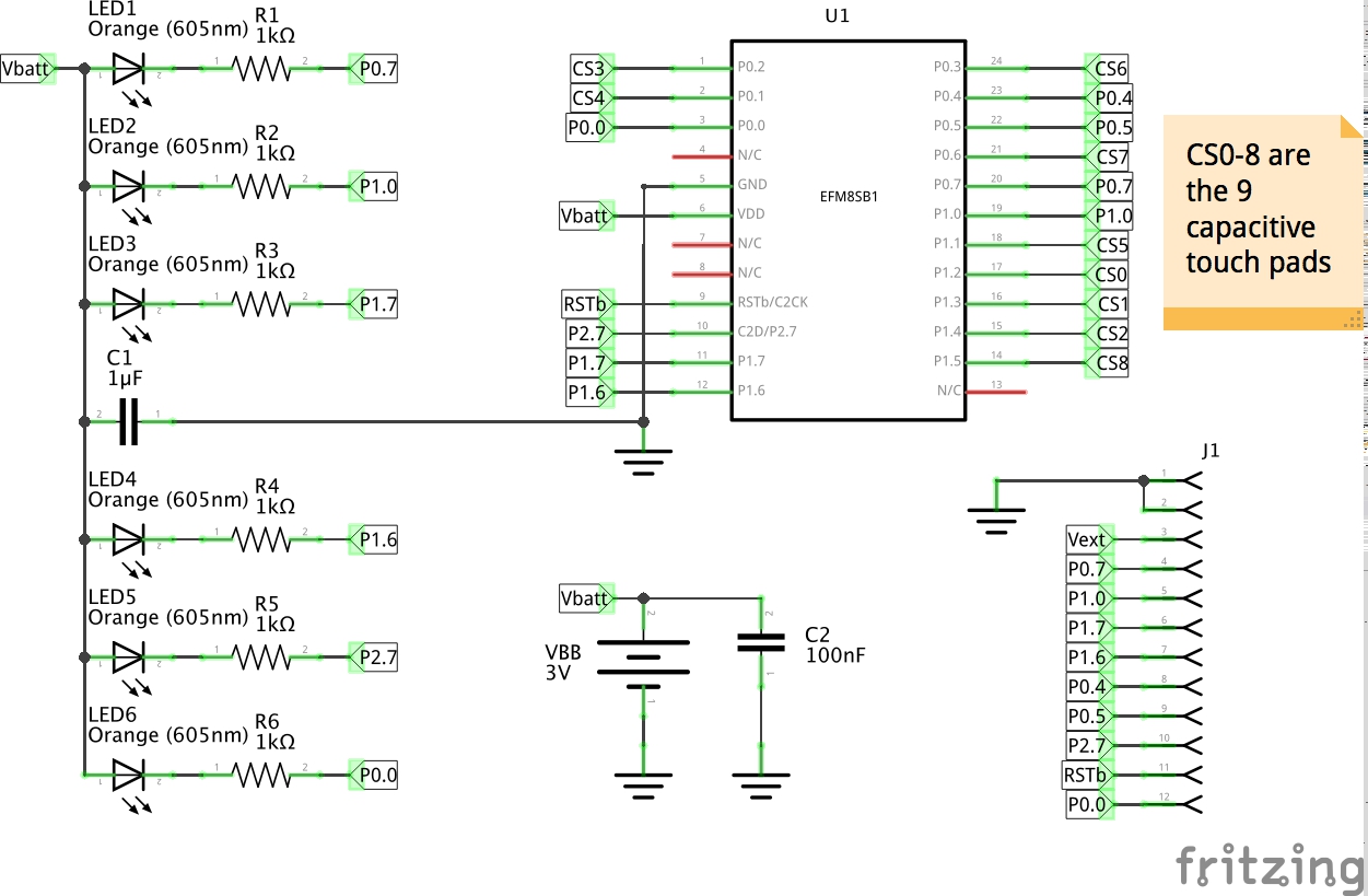
The Touchy schematic is available in the OSH files repository. But as is my routine, I like to redraw circuits to get better acquainted with exactly how they are put together. I’ll usually use Fritzing for this as it is very quick, but note I fudge details (like the microprocessor is not really DIP24):
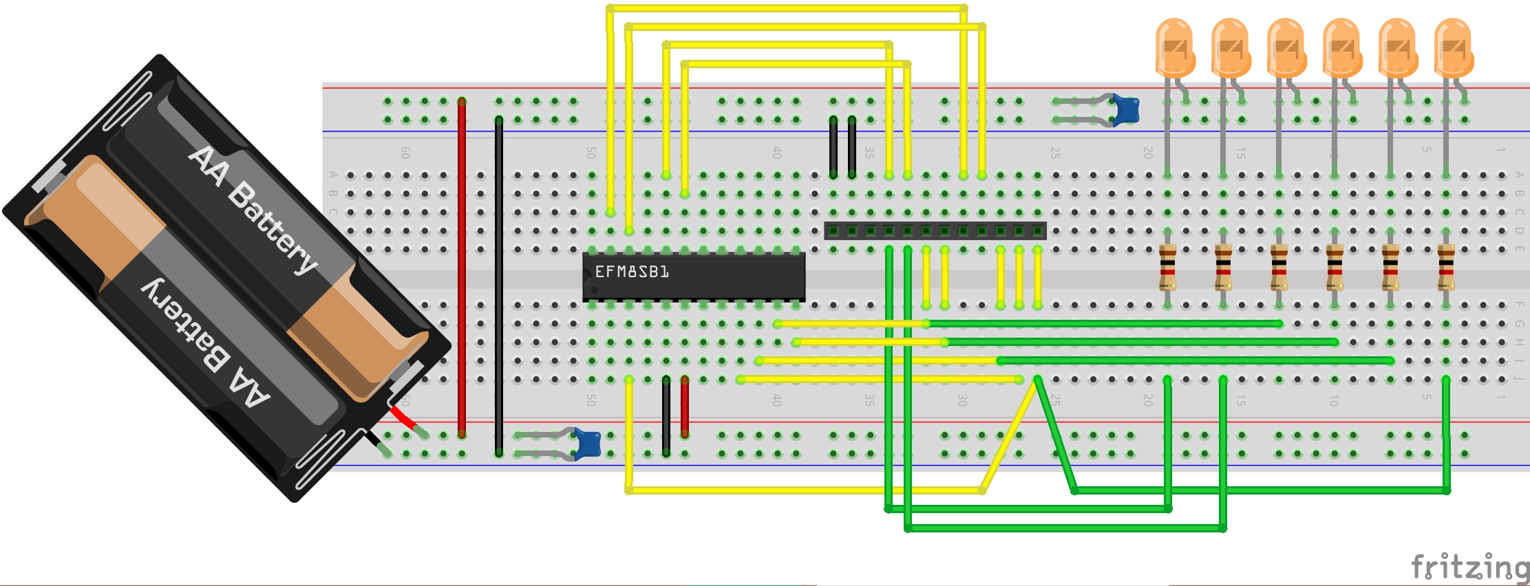
If you could get the Sleepy Bee in DIP24 package (or provide a DIP24 adapter), here’s how this could look on a breadboard:


Credits and References
- Touchy - in the Boldport shop
- Touchy - project page
- Touchy - OSH files on GitHub
- Touchy - club community site, packed with resources for the project
- Touchy schematic - OSH files on GitHub
- BC_Touchy_Firmware
- Boldport Project # 7 Touchy - tutorial by #DefineElectronics
- #8 Assembling the Touchy - tutorial video by #DefineElectronics
- #7 How to upload code to the Touchy board via the serial Bootloader - tutorial video by #DefineElectronics
- EFM8SB1 Sleepy Bee microcontroller - parts.io
- EFM8 Sleepy Bee 8-bit Microcontrollers - silabs
- EFM8 datasheet
- AN0828: Capacitive Sensing Library Overview
- AN0829: Capacitive Sensing Library Configuration Guide
- Simplicty Studio
- ..as mentioned on my blog

