
#266 TheCuttle
A bare-bones Arduino-compatible kit from The Boldport Club (Project #6).
Notes
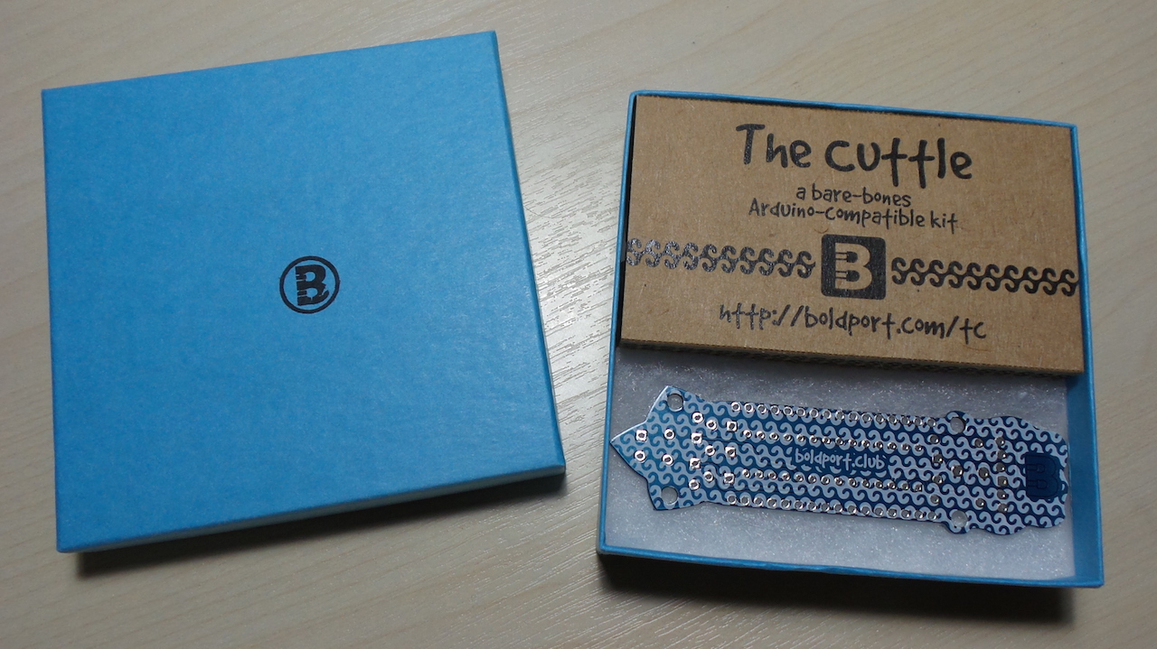
The Cuttle is a bare-bones Arduino-compatible soldering kit. It was first designed as commissioned work for Embecosm, who made it open source hardware.
What’s different about this board? It is by far the most beautiful Arduino-like board I own!
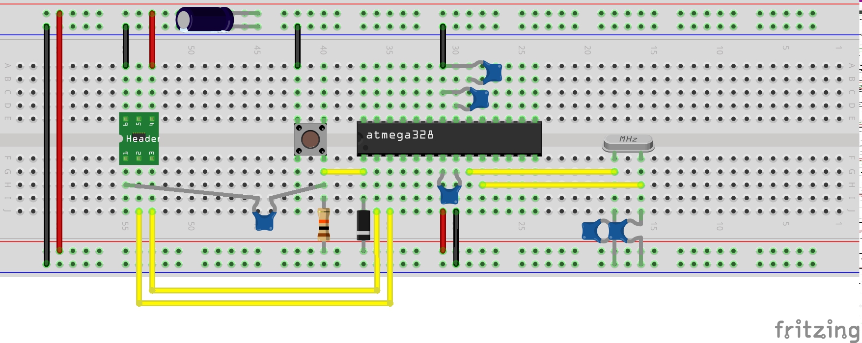
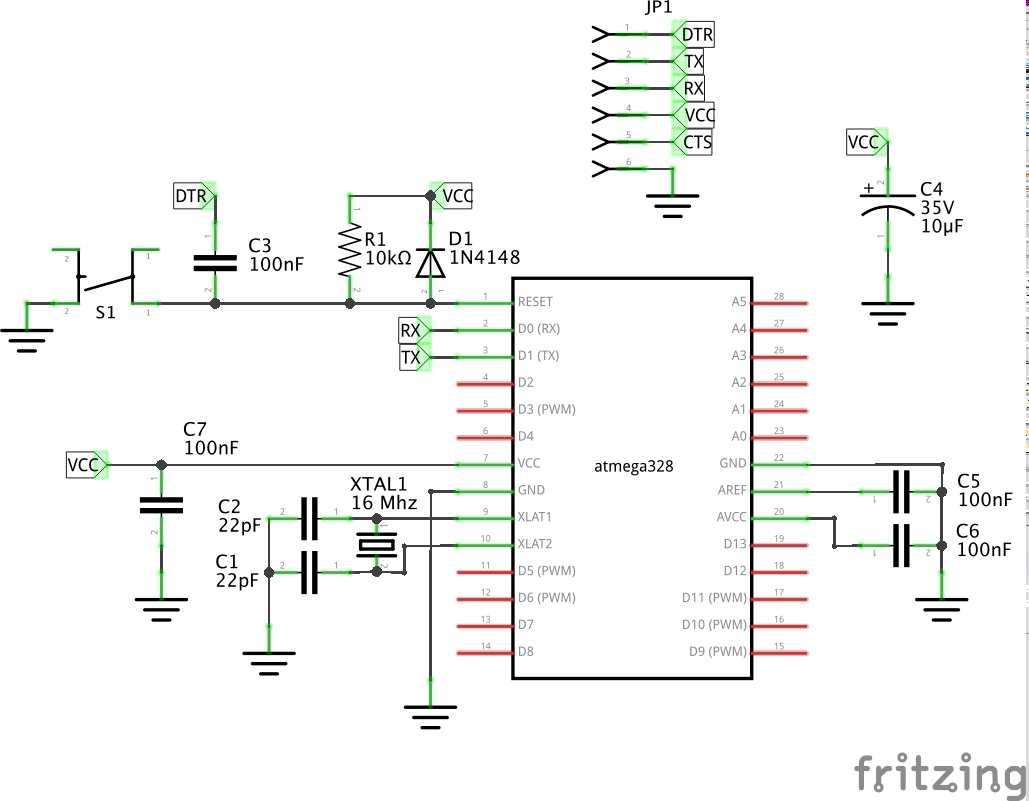
Note: I’ve also created a Fritzing part for the Cuttle module, see FritzingParts/TheCuttle.
Parts & Unboxing
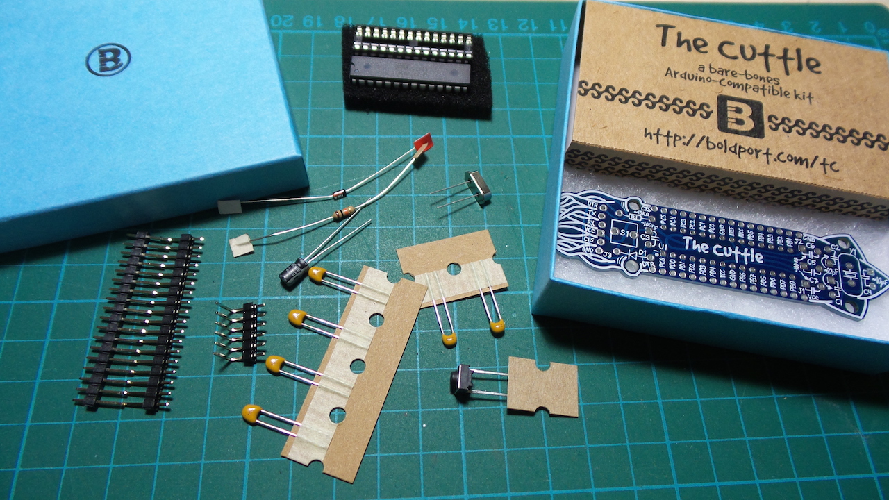
| Ref | Item | Qty |
|---|---|---|
| S1 | Tactile switch, TE Connectivity, FSM4JRT | 1 |
| U1 | ATMega328-PU microcontroller, Atmel, ATMEGA328-PU | 1 |
| C1,2,3,4 | 0.1µF ceramic capacitor, Multicomp, MC0805Y104M500A2.54MM | 4 |
| C5,6 | 22pF ceramic capacitor, Multicomp, MC0805N220J500A2.54MM | 2 |
| C7 | 10µF electrolytic capacitor, Multicomp, MCMR35V106M4X7 | 1 |
| R1 | 10KΩ resistor, Multicomp, MCF 0.25W 10K | 1 |
| D1 | Small signal diode, Multicomp, 1N4148 | 1 |
| Q1 | 16MHz crystal, TXC, 9B-16.000MAAJ-B | 1 |
| - | DIP socket, TruConnect, DS1009-28 AT1NS | 1 |
| - | 18 contacts header, Multicomp, MC34737 | 2 |
| - | 6 contacts right-angle header, Multicomp, MC34751 | 1 |
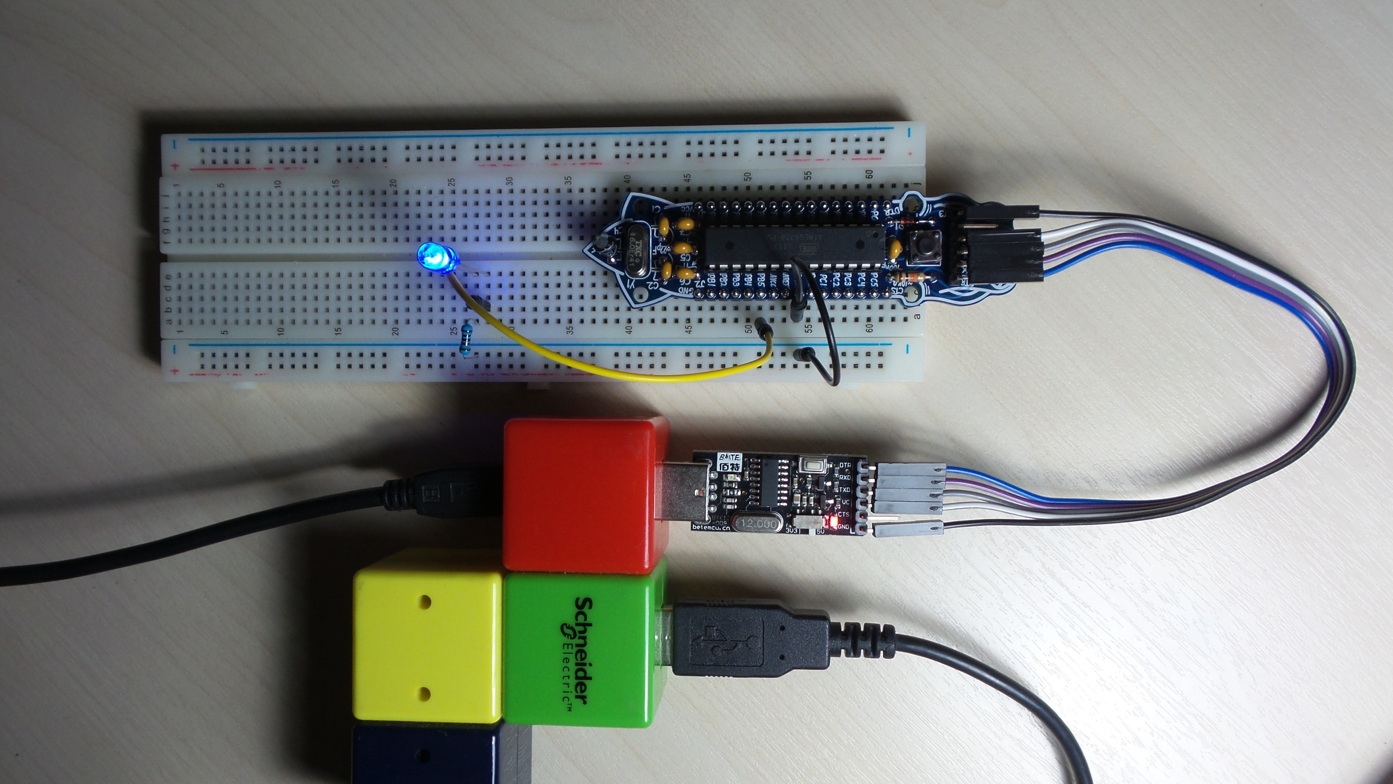
Programming the Cuttle
I’m using a cheap CH340G-based USB to UART adapter. With the correct drivers installed, it shows up in the Arduino IDE and programming works like any other Arduino board.
See the ATmega168/328-Arduino Pin Mapping for details on mapping the ATmega328 pins to Arduino port names.
| Cuttle Pin | ATmega328 Pin | Arduino Pin |
|---|---|---|
| DTR* | - | - |
| PC6 | PCINT14, RESET | RESET |
| PD0 | PCINT16/RXD | D0, RX |
| PD1 | PCINT17/TXD | D1, TX |
| PD2 | PCINT18/INT0 | D2 |
| PD3 | PCINT19/OC2B/INT1 | D3~ |
| PD4 | PCINT20/XCK/T0 | D4 |
| VCC | VCC | VCC |
| GND | GND | GND |
| PB6 | PCINT6/XTAL1/TOCS1 | (crystal) |
| PB7 | PCINT7/XTAL2/TOCS2 | (crystal) |
| PD5 | PCINT21/OC0B/T1 | D5~ |
| PD6 | PCINT22/OC0A/AIN0 | D6~ |
| PD7 | PCINT23/AIN1 | D7 |
| PB0 | PCINT0/CLKO/ICP1 | D8 |
| VCC* | VCC | VCC |
| GND* | GND | GND |
| PB1 | PCINT1/OC1A | D9~ |
| PB2 | PCINT2/OC1B/SS | D10~ |
| PB3 | PCINT3/OC2A/MOSI | D11~ |
| PB4 | PCINT4/MISO | D12 |
| PB5 | PCINT5/SCK | D13 |
| AVCC | AVCC | VCC |
| AREF | AREF | AREF |
| GND | GND | GND |
| PC0 | PCINT8/ADC0 | A0 |
| PC1 | PCINT9/ADC1 | A1 |
| PC2 | PCINT10/ADC2 | A2 |
| PC3 | PCINT11/ADC3 | A3 |
| PC4 | PCINT12/ADC4/SDA | A4 |
| PC5 | PCINT13/ADC5/SCL | A5 |
| CTS* | - | - |
The Cuttle pins marked * are extra pins on the PCB that don’t directly correspond to an ATmega328 pin or are duplicates.
Construction
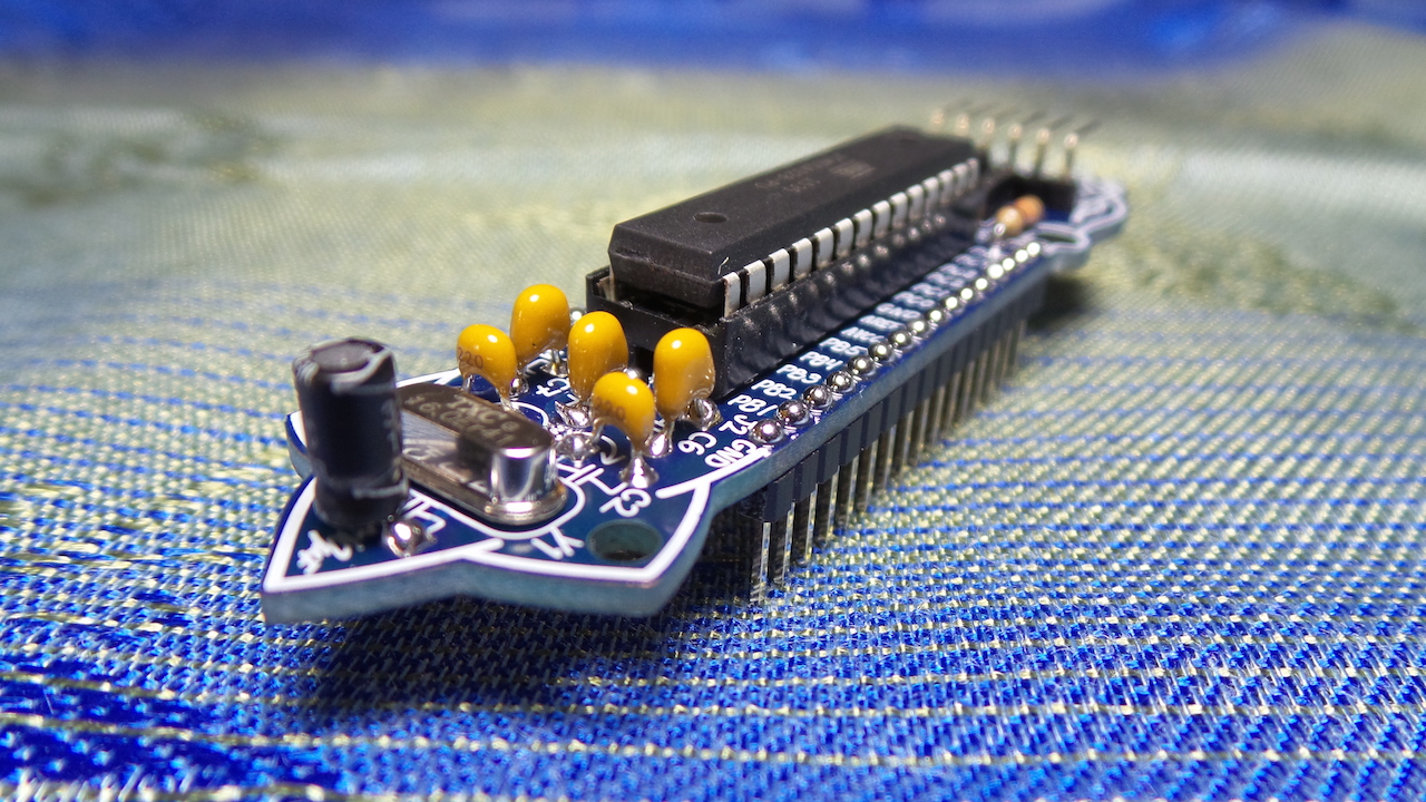
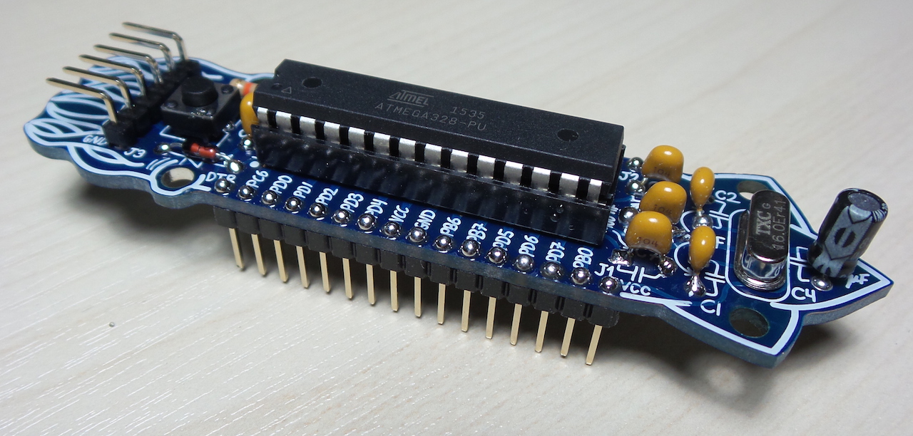
Finished assembly:
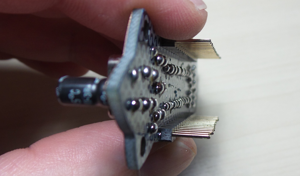
Underside; I haven’t cleaned it after soldering:
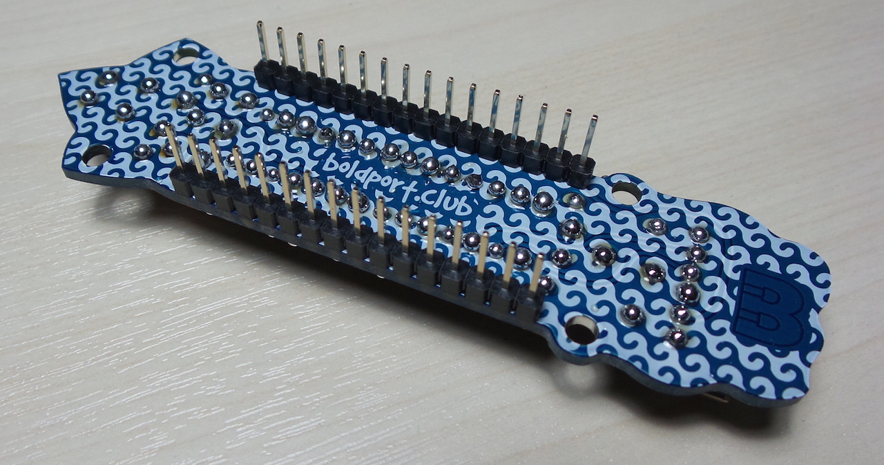
Nice “Boldport” solder domes! A few flux splatters I haven’t cleaned up. I also made a bit of a mistake with the pins - I pushed them flush from the top but forgot to ensure they were fully aligned.
Credits and References
- TheCuttle - in the Boldport shop
- TheCuttle - project page
- TheCuttle - OSH files on GitHub
- TheCuttle - club community site, packed with resources for the project
- ATMEGA328P datasheet - parts.io
- USB to TTL converter UART module CH340G CH340 3.3V 5V switch - the USB programming adapter I’m using
- ATmega168/328-Arduino Pin Mapping
- FritzingParts/TheCuttle - a Fritzing part for the Cuttle module
- ..as mentioned on my blog