#477 Rakit Drum Synth
Building the Rakit Drum Synth kit - a very nicely produced clone of the classic Boss PC-2/AMDEK PCK-100 percussion synthesizer.

Notes
I just had some fun building the Rakit Drum Synth kit. It’s a very well produced kit that recreates the classic Boss PC-2/AMDEK PCK-100 percussion synthesizer, staying very true to the original design and components.
Here’s the demo from Rakit:
Circuit Design
The Rakit Drum Synth is based on the classic Boss PC-2/AMDEK PCK-100 percussion synthesizer, with mods:
- Attack on/off
- VCO & LFO wave shape selection
- Pitch CV input
In layout and parts selection it is very close to this old AMDEK PCK-100 schematic:

The design uses a number of legendary parts that are interesting in themselves including the: the JRC4558 JFET opamp, and Rohm BA6110 voltage controlled op-amp in an unusual SIP-9 package. These parts are common in many famous products from guitar pedals to synths. Whether these parts are “key” to the sound is a matter of great debate;-)
I discovered interesting attempts to recreate the (now largely unobtainium) BA6110, including this PCB design on OSHPark.
Parts
| Component | Qty | Checked & Installed |
|---|---|---|
| 3.5mm Mono Socket | 3 | √ |
| A100k Log Potentiometer | 4 | √ |
| B504 500k Linear Potentiometer | 1 | √ |
| B102 1k0 Linear Potentiometer | 1 | √ |
| 50k Trim potentiometer | 2 | √ |
| 2.1mm/5.5mm Barrel Power Socket | 1 | √ |
| Right Angle SPST Slide Switch | 2 | √ |
| Horizontal DPDT Slide Switch | 3 | √ |
| 1n0 Box Capacitor | 4 | √ |
| 3n3 Box Capacitor | 1 | √ |
| 22n Box Capacitor | 1 | √ |
| 47n Box Capacitor | 3 | √ |
| 390R 0.6W 1% Resistor | 1 | √ |
| 1k0 0.6W 1% Resistor | 5 | √ |
| 4k7 0.6W 1% Resistor | 4 | √ |
| 10k 0.6W 1% Resistor | 5 | √ |
| 22k 0.6W 1% Resistor | 4 | √ |
| 33k 0.6W 1% Resistor | 2 | √ |
| 47k 0.6W 1% Resistor | 12 | √ |
| 56k 0.6W 1% Resistor | 1 | √ |
| 100k 0.6W 1% Resistor | 11 | √ |
| 220k 0.6W 1% Resistor | 2 | √ |
| 1M0 0.6W 1% Resistor | 1 | √ |
| 4M7 0.6W 1% Resistor | 1 | √ |
| OTA IC BA6110 | 1 | √ |
| Op Amp 4558 IC | 1 | √ |
| Op Amp 358/2904 IC | 3 | √ |
| 3mm Blue LED | 2 | √ |
| Signal Diode 1N4148 | 3 | √ |
| Schottky diode IN5819 | 1 | √ |
| 2N3904 NPN Transistor | 2 | √ |
| 2N3906 PNP Transistor | 2 | √ |
| 2SC945P NPN Transistor | 2 | √ |
| 1u0 Electrolytic Capacitor | 3 | √ |
| 10u Electrolytic Capacitor | 2 | √ |
| 100u Electrolytic Capacitor | 1 | √ |
| PCB – Top, Inside, Left Wing, Right Wing | 4 | √ |
| Battery Snap to Barrel | 1 | √ |
| Rubber Tube | 4 | √ |

Construction
Rakit have a very clear assembly guide online. Recommended build sequence:
- IC’s
- transistors
- diodes
- electrolytic capacitors
- LEDs
- resistors (all vertically mounted)
- Trimmers
- box capacitors (not polarised)
- slide switches
- 3.5mm mono sockets
- piezo disc wires
- potentiometers and switches
- rubber feet
My only embellishment on the procedure was to go for Boldport-style solder domes with my favourite 2% Ag solder;-)
Fitting the all the semi-conductors and electrolytic capacitors..

With remaining caps,resistors, slide switches and sockets..

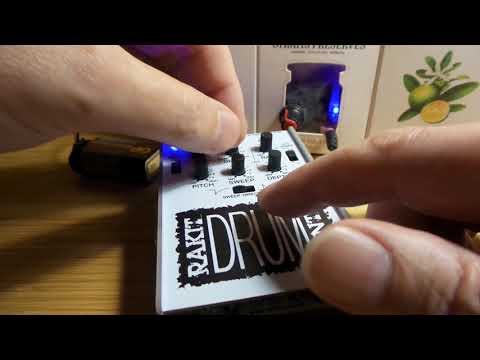
Attaching the piezo pad:

And seating the pots and top-panel switches..

All finished! Rear view..

And from the top..

Here’s a quick demo.. just mucking around trying to discover the range of sounds it can produce: