
#499 HS088 Low-voltage Amplifier
Adding a low-voltage BJT class A amplifier for the HS088 Audio Effects Chip.
Here’s a quick demo..
Notes
The HS088 audio effects chip encodes a “ding dong” wave, but like many effects chips it cannot drive a speaker particularly well in its default circuit configuration.
Adding an LM386 is a very simply way to provide amplification, but that requires a power supply of 4-5 volts. But I was interested to explore circuit ideas for providing decent amplification at lower voltages - specifically with a 3V CR2032 coin cell.
There are other amplifier-on-a-chip options that work at these voltage levels (such as the TDA2822), but first I decided to try a descrete BJT design.
My first test was with a simple single-stage common-emitter design (R1=6.8kΩ, R2=4.7kΩ, Rc=50Ω, Re=10Ω with 47µF bypass - designed for Icq=40mA). Unloaded, it achieved excellent amplification, but proved to be very poor at power transfer to the speaker.
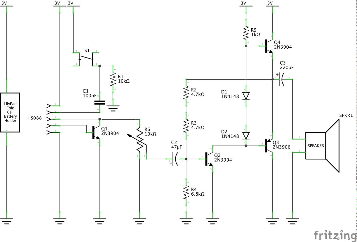
Adding a push-pull output stage started to produce some more decent results with an 8Ω speaker. The final circuit described below is an adaptation of a design from deeptronic that was in turn inspired by a design from Bowden’s.
Circuit Design
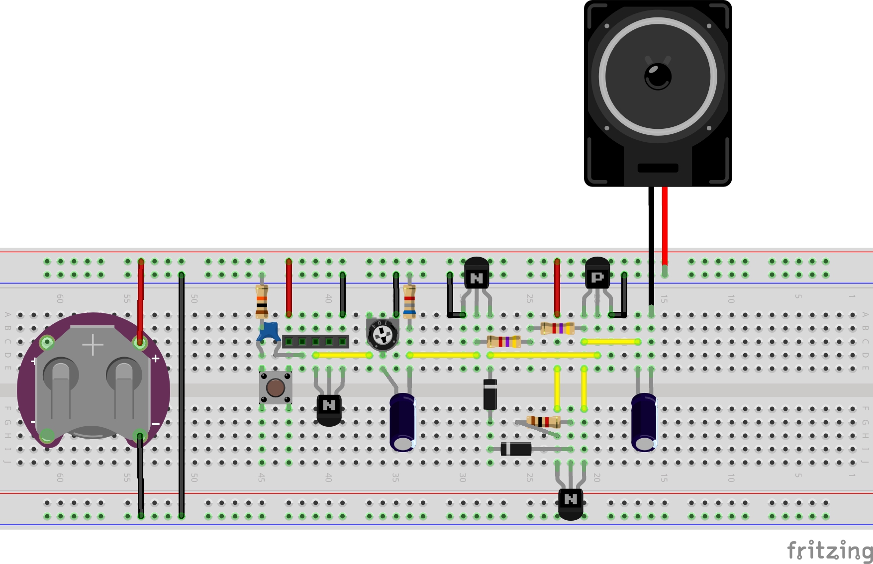
Testing on a breadboard:
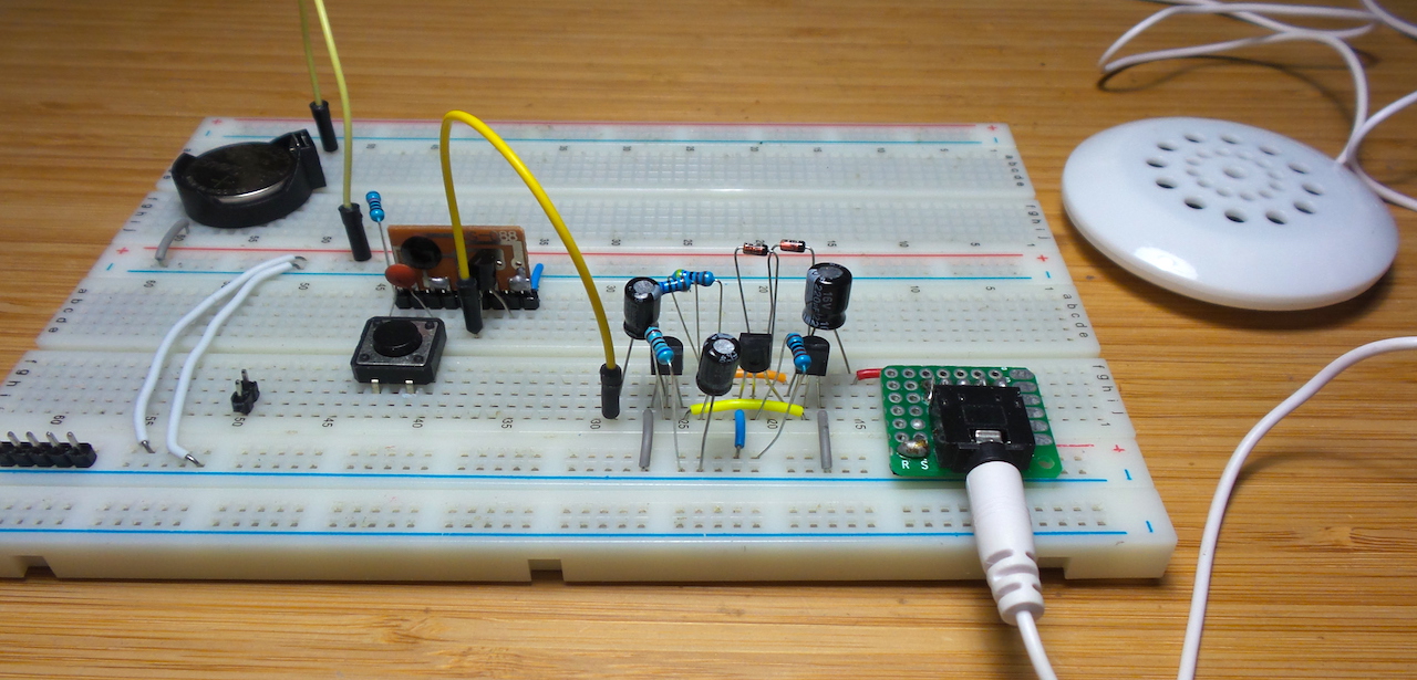
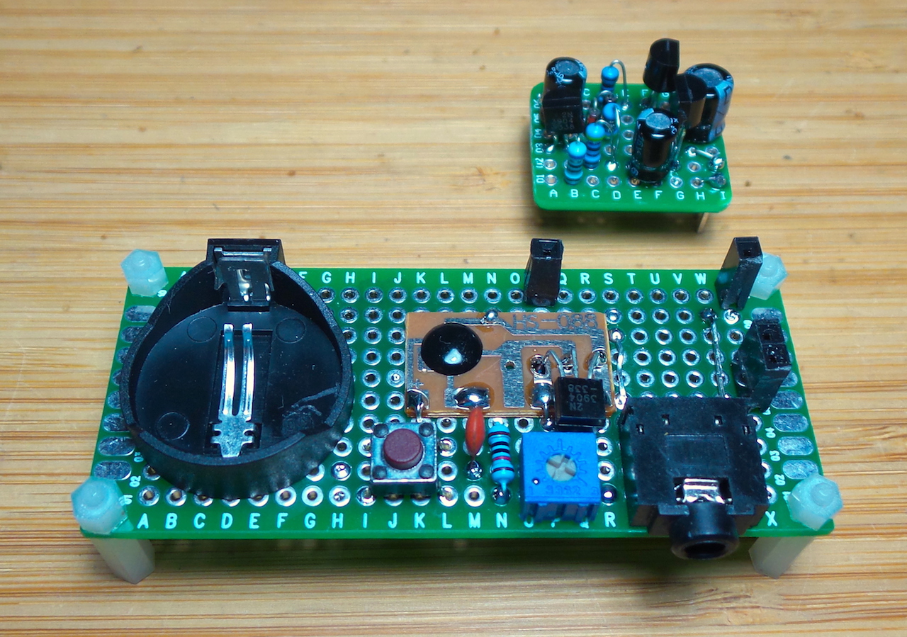
Building an Amplifier Module
After verifying component values on a breadboard, I but the amplifier circuit on a small piece of protoboard.

I’ve taking some measurements of the amplifier performance with a 1kHz sine wave and 3V power supply.
Test 1: Adjusted for minimum distortion
Adjusting the input attenuation for the sweet spot for minimum distortion, gain is around 19.
- CH1 (yellow) : 400mV input signal (before attenuation)
- CH2 (blue) : unloaded output (~475mV)
- CH3 (red) : ~25mV input signal (after attenuation)
Test 2: Maximum Input Without Clipping
About 40mV is the largest input signal that can be handed before the output starts clipping. The output is quite distorted at this point though.
- CH1 (yellow) : 400mV input signal (before attenuation)
- CH2 (blue) : unloaded output (~1000mV)
- CH3 (red) : ~40mV input signal (after attenuation)
Test 3: Overdrive!
The circuit is completely overdriven with a 400mV input. The output is essentially a square wave at this point!
- CH1 (yellow) : 400mV input signal
- CH2 (blue) : ~2V unloaded output
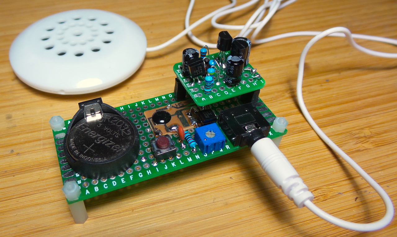
Final Build
Finally, putting it all together. First, as always, verify on a breadboard:
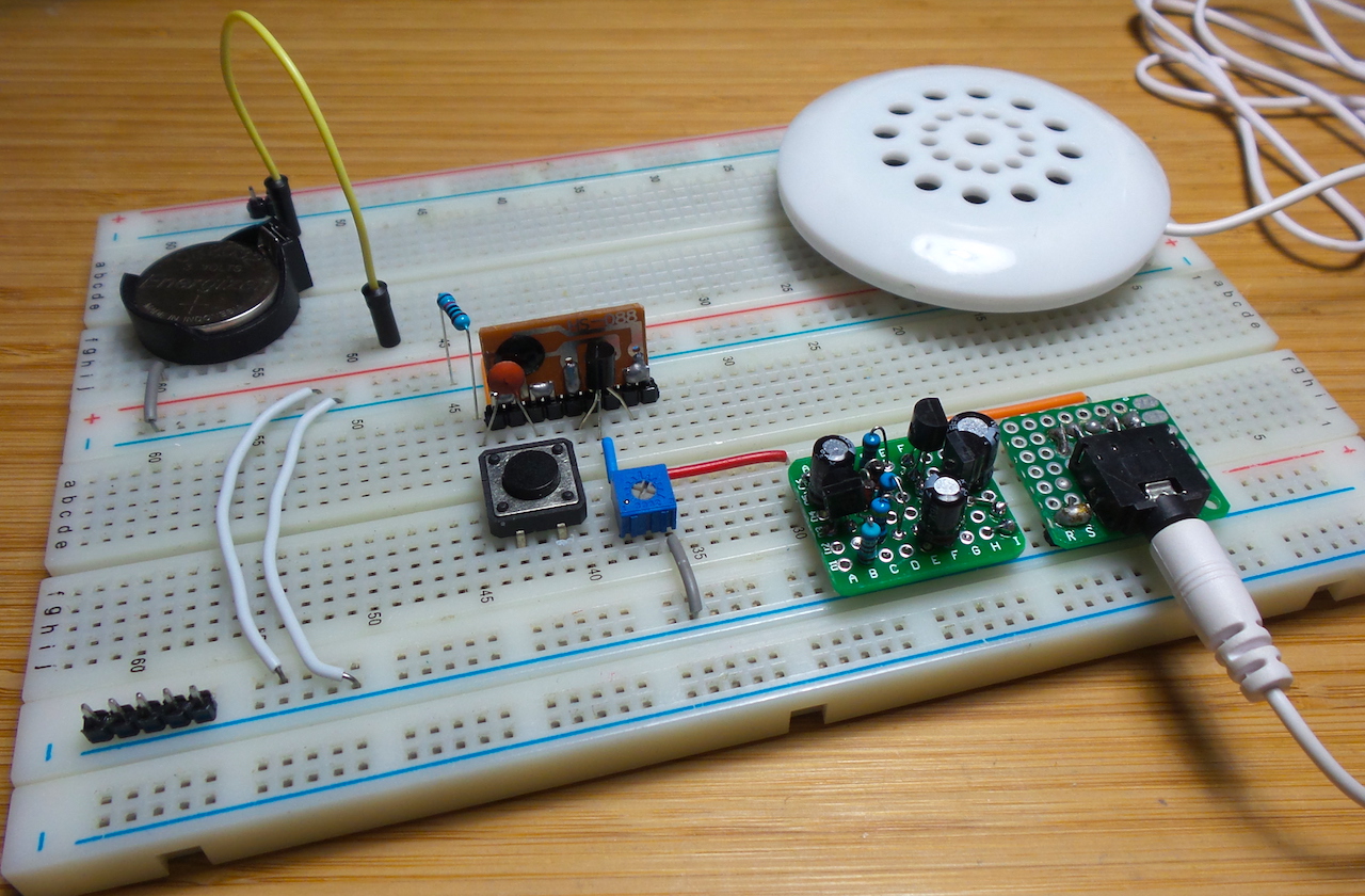
I used another strip of protoboard as the mainboard to mount the:
- HS088 chip and supporting components (trigger switch, output transistor)
- volume control
- CR2032 battery holder
- 3.5mm phone jack
- amp module mounting
The final build, with volume adjusted for maximum output without distortion procudes an amplified output that is perhaps 3x the apparent volume of the unamplified HS088 module. I don’t have an SPL meter to verify this with a measurement (yet).
Credits and References
- LEAP#359 HS088 Audio Effects Chip
- 2N3904 datasheet
- 2N3906 datasheet
- LM386 datasheet
- TDA2822 datasheet
- Small Audio Power Amplifier Using 3 Transistors - deeptronic design use in this project
- 3 Transistor Audio Amp (50 milliwatt) - inspiration for the deeptronic design